3B1A-6 POWER STEERING GEAR UNIT REPAIR
ADJUSTER PLUG
Figures 1, 10 thru 2 2
Tools Required:
J 4245 Internal Snap Ring Pliers,
J 8524-2 Bearing Seal Remover
J 7079-2 Driver
Disassemble
•
If the seal (17) is to be replaced, install the
adjlister plug (19) loosely in the gear housing.
1.
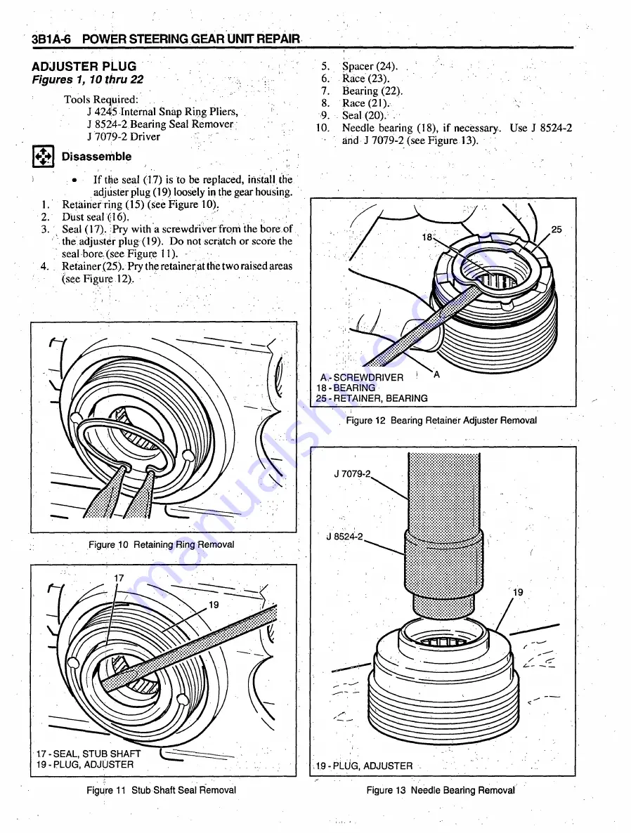
Retainer ring (15) (see Figure 10).
2.
Dust seal (16).
3.
Seal (17). Pry with a screwdriver from the bore of
the adjuster plug (19). D o not scratch or score the
seal bore, (see Figure 11).
4.
Retainer (25). Pry the retainer at the t wo raised areas
(see Figure 12).
5.
Spacer (24). ,
' ;
6.
Race (23).
1
7.
Bearing (22).
8.
Race (21).
9.
Seal (20). .
10. Needle bearing (18), if necessary. Use J 8524-2
and J 7079-2 (see Figure 13).
Figure 12 Bearing Retainer Adjuster Removal
Figure 13 Needle Bearing Removal
Summary of Contents for C Series 1993
Page 1: ......
Page 12: ...OA 6 GENERAL INFORMATION Figure 11 Allison Transmission I D Location ...
Page 44: ...3B1A 2 POWER STEERING GEAR UNIT REPAIR Figure 1 710 Power Steering Gear ...
Page 62: ......
Page 75: ...3B3 2 POWER STEERING COMPONENTS TRW ROSS ...
Page 121: ...5H 16 AIR BRAKE VALVES Figure 21 Bendix Proportioning Relay Valve Components ...
Page 147: ...5J 10 AIR COMPRESSOR AND GOVERNOR 286 F9051 Figure 18 Bendix BX 2150 Compressor Components i ...
Page 204: ...MODEL 295 TBI UNIT 6C1 3 F7973 Figure 3 Model 295 TBL Unit ...
Page 251: ...6D4 6 37 MT STARTER MOTORS V3022 Figure 8 37 MT Components ...


