GBESS 2.4_4.8KWH system user manual
22
L
N
L
N
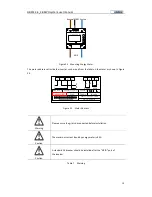
Figure 28 LOAD connector(F4) and wiring
Line definition: the red is power line (L), the black is neutral line (N), the yellow green is grounding line
(PE).
3.3.2 RS485 Communication Line
GMDE inverter uses RJ45 jacks as the RS485 communication port. The RJ45 plug pin allocation is
illustrated by figure 25.
Figure 29 RJ45 plug pins allocation
Pin No.
Illustration
1
--
2
--
3
Data+
4
GND
5
GND
6
Data-
7
5V
8
5V
Table 8 RJ45 plug pins allocation
3.3.3 System Connection
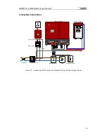
Please refer to table below and connect the power lines, communication lines with correspond ports
on the device respectively.

