4
3
2
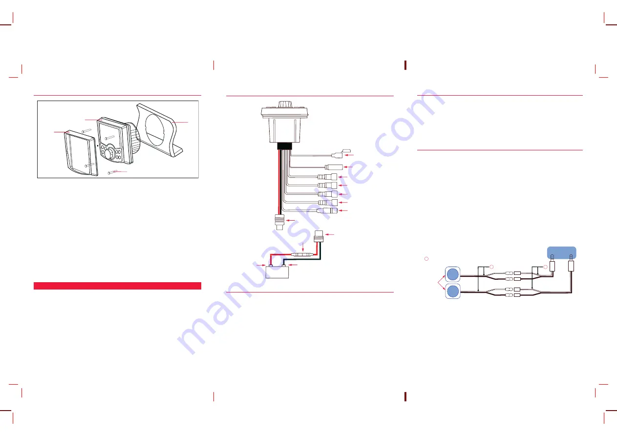
MOUNTING THE RADIO
Source Unit
Trim Bezel
Mounting Screws
Panel
NOTE:
Select a suitable mounting location. Then examine the area behind the panel to
determine if there is sufficient access for routing the cables and fitting the mounting
screws. For panels of 6 – 9 mm thickness such as aluminium, plywood or fibreglass, the
unit can be mounted using the 12 mm screws supplied (refer the diagram above).
1.
Cut out a circular hole 80 mm (3.15 inch) in diameter on your mounting
location. Keep in mind that at least 140 mm (5.5 inch) depth is needed to
mount the radio.
IMPORTANT
: Do not mount this unit where it can be submerged in water.
2.
Use the supplied mounting template to mark and drill holes for the four
mounting screws.
3.
Secure unit with the supplied screws.
4.
Press on the Trim Bezel to the front side of the unit.
5.
Plug in all wiring harnesses and cables.
Refer the wiring diagram in this guide for details.
WIRING & CONNECTIONS
When connecting the GR350BT to the electrical system of your vessel, please refer the
wiring diagram on the next page.
CAUTION
: The GR350BT is designed for vessels with a 12 Volt DC negative (−) ground
(earth) electrical system only. Reverse polarity or over-voltage connection will result in
internal damage to your unit, voiding the warranty and requiring servicing by qualified
personnel.
WIRING DIAGRAM
USB
Radio antenna
Front right speaker
Front left speaker
Rear right speaker
Rear left speaker
Auxiliary input
DC Cable
DC Cable
Fuse 15 Amp
Black - ve
Red + ve
12 V battery
ANTENNA INSTALLATION AND CONNECTION
It is essential to select a good quality AM/FM antenna. The antenna should be mounted
in a position as high as practically possible to ensure good reception, especially in areas
with low signal strength. When installing the antenna, ensure a minimum clearance
of around 20 cm from bow or stern rails or windscreen frames etc. Place the antenna
at least 1 metre from two-way radio antennas to minimise interference from radio
transmissions.
To connect the antenna to your radio:
Plug the antenna lead into the fly-leaded antenna socket on the rear of the unit. The
socket accepts a standard AM/FM radio bayonet type connector.
NOTE
: The antenna socket is not water-proof. Ensure that all connections are
water-proofed.
DC CONNECTIONS
While connecting the radio, refer the wiring diagram in this guide.
1.
Connect the RED power lead to the Positive (+) side of the battery or to an
accessory point in the vessel or vehicle’s fuse box that provides a +12 Volt
DC connection.
2.
Connect the BLACK power lead to the Negative (−) side of the battery or to
a ground point in your vessel or vehicle.
SPEAKER CONNECTIONS
When connecting the speakers to your radio, the speakers should be connected to the
respective FRONT (left/right) and REAR (left/right) speaker fly-leaded sockets at the back
of the unit.
The GR350BT radio is supplied with four 3.5 mm speaker adapter leads. The speaker
adapters are labelled and should be matched with the labels on the speaker socket fly-
leads to ensure correct speaker phasing. Incorrect polarity (speaker phasing) will result
in a significant reduction of bass response and stereo effect.
When connecting the speakers, observe the correct speaker polarity by matching the
white stripes on the speaker leads with the white stripes on the adaptor cable, as
shown in the connections diagram below. Connect all four speakers as shown in the
connection diagram below. If you wish to connect only two speakers, connect these
to the Front speaker sockets and adjust the Fader control to the FRONT speakers. To
protect against water ingress, replace the protective covers on any unused speaker
sockets.
GR350BT Radio
L
R
1
1
1
Bullet Connectors
White Stripe
Speakers
SPEAKER ADAPTOR LEADS
CAUTION
:
1. The GR350BT is a four-speaker system that requires two separate wires for each
speaker. DO NOT touch the speaker wires together or allow them to touch other wiring
or the vessel ground (earth).
2. The use of speakers with an impedance of LESS than 4 Ohms is NOT recommended,
as they will cause excessive loading of the GR350BT’s audio output circuit and may
result in the radio overheating.


