r c 9 0 0 B t
i n s t r u c t i o n m A n uA l
PA G E 5
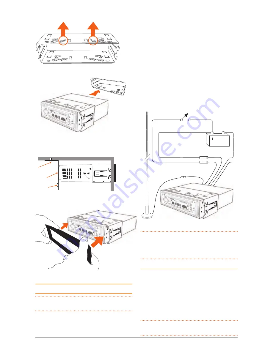
4. Bend the tabs to secure the frame in the recess.
5. insert the rc900Bt in the mounting frame.
6. Attach the support strap provided to the rear
of the rc900Bt and fastened strap to dash
framework or added support.
ScreW
STrap
ScreW
7. reattach the front panel surround.
ELECTRICAL WIRING
Dc connections
cauTioN:
the rc900Bt is designed for vehicles
with a 12 V negative ground electrical system only!
referring to the wiring diagram on this page:
1. connect the yElloW wire directly to the positive
terminal of the vehicle’s battery, or to a point
that has +12 volts available at all times. this lead
maintains the memories within the rc900Bt and
is the main power source for the unit.
2. connect the rED wire to the vehicle’s +12 volt
supply via an appropriate isolating switch or
circuit breaker. this lead enables the radio to be
switched ON and OFF. Alternatively, this wire can
be connected directly to the battery’s positive
terminal and the rc900Bt switched on and oFF
using it’s own controls.
3. connect the BlAcK wire to the battery’s negative
terminal or to the common negative bus in the
electrical system.
ANTENNA
RED
BLACK
BLUE
AUTO
ANTENNA
12V+ OUT
NEG
0.5 AMP
15 AMP
MEMORY 12 V+
IGN SWITCH ACC
YELLOW
NoTe:
the blue wire on the wiring loom supplies
12 volts when the rc900Bt is switched on and can
be used to turn on an external device, like the GME
GA9800 amplifier.
Speaker connections
When connecting the speakers, observe the correct
polarity as shown in the diagram above. incorrect polarity
will result in a reduction of bass response and stereo
effect. the use of speakers with an impedance of less
that 4 Ohms is not recommended, as they will cause
excessive loading of the RC900BT’s output circuit and
may result in the radio overheating.
cauTioN:
The RC900BT is a four-speaker system
that requires 2 separate wires for each speaker.


