background image

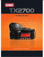
TX2700 

INSTRUCTION MANUAL 

PAGE 9

GME have a large range of suitable 27 MHz CB antennas to 
suit most installations and applications. We recommend you 
contact your local GME dealer for advice.

Connect the antenna cable to the rear antenna socket using a 
PL259 coaxial connector.

NOISE SUPPRESSION

27 MHz CB radio can be prone to electrical and ignition 
interference. The reason is that electrical noise is a form 
of AM transmission similar to that used by your radio and 
your radio’s receiver is very sensitive. In most cases, ignition 
noise can be greatly reduced or eliminated by selecting the 

Noise Limiter (NL)

 key on the radio. In some severe cases, 

additional suppression may need to be fi tted to the ignition 
system of your vehicle, in which case we recommend you 
consult an Auto Electrician for advice specifi c to 
your installation.

FITTING THE MICROPHONE

The microphone uses a miniature 6 pin telephone style plug 
and socket. 

Fitting microphone to the front panel

1.   Position the microphone plug so the plastic tab faces 

sideways to the left on the front panel. Press the plug into 
the socket until it ‘clicks’.

2.   Gently press the rubber strain relief into the hole 

surrounding the socket so that the slot around the strain 
relief fi ts neatly inside the lip of the hole.

Fitting microphone to the rear panel

1.   Position the microphone plug so the plastic tab faces 

upwards on the rear panel. Press the plug into the socket 
until it ‘clicks’.

2.   Gently press the rubber strain relief into the hole 

surrounding the socket so that the slot around the strain 
relief fi ts neatly inside the lip of the hole. 

Removing the microphone

1.   Squeeze the rubber strain relief near the front panel to 

disengage the slot, and slide the strain relief back along 
the microphone cord.

2.   Press the small plastic tab on the microphone plug 

towards the plug to unlock it, while gently pulling the plug 
outwards. If the plug does not come out easily, the tab has 
not released correctly and should be pressed again. You 
may need a small bladed screwdriver for this task, as the 
tab can be diffi cult to reach with your fi ngers.

If required, replacement microphones are available with plug 
and rubber boot already fi tted.

Rear Microphone Connection

The TX2700 also has a rear microphone connection. To use 
this facility, remove the rubber grommet on the rear of the 
radio and insert into the front panel of the radio. Insert the 
microphone plug into rear microphone connection.

Microphone Extension Lead

The LEM6P is a 4 metre microphone extension lead that can 
be fi tted to the microphone socket. 

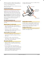
Cable

Screwdriver

Locking Lever 
move to left to 
release Plug

Cable entry hole

Summary of Contents for TX2700

Page 1: ...27 MHz CB radio I N S T R U C T I O N M A N U A L ...

Page 2: ...ed into almost any mounting location in your motor vehicle or motorbike Please read this manual thoroughly to ensure you get the best from the TX2700 s features For users in New Zealand South Africa or P N G Please refer to amendment for local frequencies channel allocations and licensing requirements CONTENTS FEATURES 3 ACCESSORIES SUPPLIED 3 OPTIONAL ACCESSORIES 3 CONTROLS 3 Front Panel 3 Rear P...

Page 3: ...PLIED TX2700 Radio Unit Microphone Clip Mounting Cradle DC Lead Instruction Manual Screw Pack Microphone If any items are missing or damaged please contact your retailer or place of purchase OPTIONAL ACCESSORIES MK200B Flush mounting kit LEM6P 4 metre microphone extension lead CONTROLS FRONT PANEL REAR PANEL PRI DW SCAN NL DIM Microphone Socket Channel Selector Speaker LCD Display Volume Squelch P...

Page 4: ... DATE MAY 14 2007 C TX BUSY SCAN DW PRI M NL EXT PRG FUNCTION CHANNEL DISPLAY TX RX RX SENSITIVITY SCAN DUAL WATCH PRIORITY CHANNEL SCAN MEMORY NOISE LIMITER EXTERNAL MICROPHONE PC PROGRAMMING DISPLAY NO 1 2 3 4 5 6 7 8 9 10 11 Channel Number TX BUSY SCAN DW PRI M NL EXT PRG Transmit Indicator Busy Indicator RX Sensitivity Scan Dual Watch Priority Channel Scan Memory Noise Limiter External Microph...

Page 5: ...hone Hold the microphone 2 6 cm from your mouth and slightly to one side so your voice does not project directly into the microphone Speak at a normal voice level Your TX2700 has a built in speech processor which automatically controls the level of your transmitted voice It is not necessary to raise your voice or shout into the microphone NOISE LIMITER The NL key activates an extremely effective n...

Page 6: ...be cancelled To return to the previously selected channel Press the Priority key again DUAL WATCH Dual Watch in CB mode allows your TX2700 to monitor both the Priority channel and another selected channel by quickly switching between them Any signals received on the Priority channel take precedence over signals on the selected channel To use the Dual Watch feature adjust the Squelch control so the...

Page 7: ...Use 16 27 155 MHz General Use 17 27 165 MHz General Use 18 27 175 MHz General Use 19 27 185 MHz General Use 20 27 205 MHz General Use 21 27 215 MHz General Use 22 27 225 MHz General Use 23 27 255 MHz General Use 24 27 235 MHz General Use 25 27 245 MHz General Use 26 27 265 MHz General Use 27 27 275 MHz General Use 28 27 285 MHz General Use 29 27 295 MHz General Use 30 27 305 MHz General Use 31 27 ...

Page 8: ...en on unsealed roads The TX2700 mounting bracket is designed with a unique dual position gimbal mounting slot This design not only allows the TX2700 to be tilted over a much greater range but also provides a slim low profile mounting position for installations where space is very limited Flush Mounting Optional MK200B flush mounting kit available DC CONNECTIONS Connect the RED power lead to the posi...

Page 9: ...e strain relief fits neatly inside the lip of the hole Fitting microphone to the rear panel 1 Position the microphone plug so the plastic tab faces upwards on the rear panel Press the plug into the socket until it clicks 2 Gently press the rubber strain relief into the hole surrounding the socket so that the slot around the strain relief fits neatly inside the lip of the hole Removing the microphone...

Page 10: ...a Spurious Emissions 26 dBm Receiver Demodulated Frequency Response 300 Hz to 3 kHz 1 3 dB Receive Sensitivity for 12 dB SINAD 30 Modulation 110 dBm Max Squelch 80 dBm Adjacent Channel Sensitivity 55 dB Spurious Response Immunity 55 dB Conducted Spurious Radiation 57 dBm Audio Output Power 8 Ohms 2 5 watts MECHANICAL Dimensions 51 H x 94 D x 170 W mm Weight 450 grams ENVIRONMENTAL Temperature Rang...

Page 11: ...ervices supplied again 2 4 For repairs outside the warranty period we warrant our repairs to be free from defects in materials and workmanship for three months from the date of the original repair We agree to re repair or replace at our option any materials or workmanship which we are satisfied are defective 2 5 We warrant that we will perform services with reasonable care and skill and agree to in...

Page 12: ...Part Number 310428 Drawing Number 44184 3 ...

Reviews: