background image

3) Drive motor/motor;
4) Wear pads;
5) Tires and wheels;
6) Limit switches and horn;
7) Alarm and indicator (if equipped);
8) Nuts, bolts and other fasteners;
9) Brake release unit.

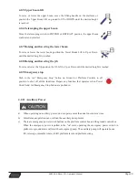
5.1.3 Maintenance hazards

a) Shut off power to all controls and ensure that all moving parts are secured from inadvertent motion

prior to performing any adjustments or repairs;

b) Never work under an elevated platform until it has been fully lowered to the full down position, if

possible, or otherwise supported and restrained from movement with appropriate safety props,
blocking, or overhead supports;

c) Do not attempt to repair or tighten any hydraulic holes or fittings while the machine is powered on

or when the hydraulic system is under pressure;

d) Always relieve hydraulic pressure from all hydraulic circuits before loosening or removing

hydraulic components;

e) Do not use your hand to check for leaks. Use a piece of card- board or paper to search for leaks.

Wear gloves to help protect hands from spraying fluid.

5.1.4 Body injury hazard

Do not operate a machine with a hydraulic oil or air leak. An air leak or hydraulic leak can penetrate 
and/or burn skin. During or after a period of running of the hydraulic system, the parts may produce 
high surface temperature, and improper contact will cause burn to skin. Overhauling or adjusting any 
part of hydraulic system can cause serious injuries. Only trained maintenance personnel are allowed to 
repair or adjust the hydraulic system.

Suggestion: access by the operator is only advised when performing a pre-operation inspection. All 
compartments must remain closed and secured during operation.

$-(%RRP/LIW 2SHUDWRU¶V0DQXDO

3DJH

Summary of Contents for 64/40 AJ-E

Page 1: ...23 5 725 6 0 18 DQXDU...

Page 2: ...RRP LIW 2SHUDWRU V 0DQXDO 3DJH L 5HYLVLRQ LVWRU DWH 8SGDWH 5HDVRQ...

Page 3: ...2 49m 8ft 2in 2 49m 8ft 2in Overall Height 2 52m 8ft 3in 2 52m 8ft 3in Platform Size 1 83 0 76m 2 44 0 91m 6ft 2ft 6in 8ft 3ft 1 83 0 76m 2 44 0 91m 6ft 2ft 6in 8ft 3ft Wheelbase 2 52 m 8ft 3in 2 52 m...

Page 4: ...s 28mph Working Temperature 25 40 13 104 25 40 13 104 Power Battery 24 2V 440Ah 24 2V 440Ah Charger 48V 60A 48V 60A Drive Motor AC 32V 3 3kw AC 32V 4 4hp AC 32V 3 3kw AC 32V 4 4hp Lift Motor AC 32V 1...

Page 5: ...RRP LIW 2SHUDWRU V 0DQXDO 3DJH LY...

Page 6: ...ndicators 2 2 1 Ground control console 2 2 2 Ground control indicator panel 2 2 3 Platform control console 2 2 4 Platform control indicator panel SECTION 3 MACHINE INSPECTION 3 3 1 General 3 3 1 1 Pre...

Page 7: ...ersion 4 2 12 Shut down and park 4 3 Transport and Lifting 4 4 3 1 Release the brake while towing 4 4 3 2 Lifting 4 4 3 3 Securing the chassis 4 4 3 4 Securing the platform 4 SECTION 5 MAINTENANCE 5 1...

Page 8: ...LDO RUN 3ODWIRUP 7KH XVHU RSHUDWRU VKRXOG QRW DFFHSW RSHUDWLQJ UHVSRQVLELOLW XQWLO KH VKH KDV UHDG DQG XQGHUVWDQGV WKH RSHUDWRU V PDQXDO DV ZHOO DV KDYLQJ RSHUDWHG WKH 0 HULDO RUN 3ODWIRUP XQGHU VXSHU...

Page 9: ...t and tested to provide safe dependable service Only authorized trained and qualified personnel shall be allowed to operate or service the machine GMG as manufacturer has no direct control over machin...

Page 10: ...als at overhead work locations The owner user operator of the machine should not accept responsibility for the operation of the machine unless properly trained 6DIHW OHUW 6 PEROV GMG manuals use symbo...

Page 11: ...required clearance Electrocution hazard Tip over hazard Tip over hazard Tip over hazard Tip over hazard Wheel load Wind speed Maximum capacity Tie down point Lanyard anchorage points Crushing hazard...

Page 12: ...ed Platform uphill 1 Lower the upper boom 2 Lower the tower boom 3 Retract the upper boom Platform downhill 1 Retract the upper boom 2 Lower the tower boom 3 Lower the upper boom Prohibit high pressur...

Page 13: ...tion from contact with or proximity to electrical current a Obey all local and governmental regulations regarding required clearance from electrical power lines At a minimum the required clearance con...

Page 14: ...not exceed the maximum platform capacity b Do not attach a platform rated at 250 kg 550 lb to machines with any other rated load See the serial label for the maximum rated capacity c The weight in op...

Page 15: ...peeds exceed 12 5 m s 28mph when the boom is raised lower the boom and do not continue to operate the machine Do not operate the machine in strong or gusty winds Do not increase the surface area of th...

Page 16: ...th items of different weight or specification j Do not replace factory installed tires with tires of different specification or ply rating k Do not use air filled tires These machines are equipped wit...

Page 17: ...rm d Do not use the machine on a moving or mobile surface or vehicle e Be sure the tires are in good condition and the lug nuts tightened besides the tightening torque should be 300N m 20 2 lb ft f Do...

Page 18: ...ll times c Do not climb down from the platform when raised d Keep the platform floor clear of debris Use extreme care while entering or exiting the platform Do not enter or exit the platform unless th...

Page 19: ...obstructions or other possible hazards c Be aware of crushing hazards when grasping the platform guard rail d Be aware of the boom position and tail swing when rotating the turntable e Operators must...

Page 20: ...of the crane have been locked out and or precautions have been taken to prevent any potential collision No stunt driving or horseplay while operating a machine Body Injury Hazard a Do not operate a ma...

Page 21: ...efore each work shift E Immediately tag and remove from service a damaged or malfunctioning machine F Be sure all maintenance has been performed as specified in this manual and the appropriate 0 servi...

Page 22: ...r charger in water or rain while charging Explosion Hazard a Keep sparks flames and lighted tobacco away from batteries Batteries emit explosive gas b Do not use tools which could produce flames to co...

Page 23: ...ruction No Name No Name 1 Foot Switch 8 Platform Console 2 Manual Storage Container 9 Main Boom upper boom 3 Sliding mid rail 10 Tower boom 4 Lanyard anchorage points 11 Ground Control Console 5 Swing...

Page 24: ...ontrol device both equip with spring so that they will back to neutral when releasing To avoid serious injury do not operate machine if any control levers or toggle switches controlling platform movem...

Page 25: ...rgency stop switch 9 Platform Ground Select Switch 10 Function Enable Switch Emergency Enable Switch 11 Display Turntable slew switch Provide 360 continuous rotating Main boom lift switch Provide main...

Page 26: ...ending descending a grade When the machine is shut down the power emergency stop switch must be positioned to the OFF position to prevent draining the batteries 8 Power Emergency stop switch A two pos...

Page 27: ...he engine is running the switch must be held DOWN to enable all boom controls When turning on the emergency power flip the switch up and use emergency power to implement all motion control functions 1...

Page 28: ...LRQ RI WKH PDFKLQH 7KH QDYLJDWLRQ NH V DOORZ IRU WKH GLVSOD RI DGGLWLRQDO LQIRUPDWLRQ VXFK DV PDFKLQH VWDWXV FRPSRQHQW LQSXW FRPSRQHQW RXWSXW DQG IDXOW FRGHV RRP LIW 2SHUDWRU V 0DQXDO 3DJH 2 2 2 Groun...

Page 29: ...J 6 VWHP 0RQLWRU DQG WKHQ QSXW 0RQLWRU the GLVSOD ZLOO VKRZ DOO VZLWFK LQSXWV LJ VHOHFWLQJ 6 VWHP 0RQLWRU DQG WKHQ 2XWSXW 0RQLWRU DOO PDFKLQH IXQFWLRQ RXWSXWV DUH GLVSOD HG LJ Figure 2 RRP LIW 2SHUDWR...

Page 30: ...e if any control levers or toggle switches controlling platform movement do not return to the OFF or NEUTRAL position when released Figure 2 9 Platform control panel only the switch number correspondi...

Page 31: ...controlling platform movement do not return to the OFF or Neutral position when released 1 Drive select switch Provides high speed and low speed a The forward position gives maximum drive speed b The...

Page 32: ...on matching the directional arrows 6 Drive Steer controller Provides drive steer controls Push forward to drive forward pull back to drive in reverse Steering is accomplished via a thumb activated roc...

Page 33: ...wer boom lift switch Provides for raising and lowering of tower boom when positioned up or down 14 Emergency enable switch After turning on the emergency power supply set to the up position depress th...

Page 34: ...ely 3 Tilt Alarm Warning Light This illuminator indicates that the chassis is on a slope As long as the X axis tilt angle of the chassis exceeds 3 or the Y axis tilt angle exceeds 5 the tilt alarm ind...

Page 35: ...lt indicator Indicates system faults 7 Soft touch indicator If light goes on soft touch function activates 8 Drive direction confirm indicator When the boom is swung over the rear tires or further in...

Page 36: ...nable light will go out and the foot switch must be released and depressed again to enable the controls Releasing the foot switch stops all platform controls To avoid serious injury do not remove modi...

Page 37: ...e procedures are required Only routine maintenance items specified in this manual may be performed by the operator d Refer to the list on the next page and check each of the items e If damage or any u...

Page 38: ...uipped 10 Nuts bolts and other fasteners 11 Platform entry mid rail or gate 12 Platform load cell 13 Lanyard anchorage points 14 Check entire machine for Cracks in welds or structural components Dents...

Page 39: ...functional test before operating the machine at all times d Inspect job site e Only use the machine as it was intended 3 2 2 Ground function check a Test Emergency Stop 1 Select a test area that is f...

Page 40: ...switch button on the platform to the on on position 2 Do not press down the foot switch 3 Attempt to activate each boom and platform function button Check test result no boom and platform functions s...

Page 41: ...the range shown The drive function should not operate 5 Move the drive enable toggle switch 6 Attempt to operate drive handle Check test result move the drive enable toggle switch and drive in low spe...

Page 42: ...ction principle The workplace inspection helps the operator determine if the workplace is suitable for safe machine operation It should be performed by the operator prior to moving the machine to the...

Page 43: ...ite is unsafe and dangerous Only trained and authorized personnel should be permitted to operate a machine If more than one operator is expected to use a machine at different times in the same work sh...

Page 44: ...duration of forward or reverse travel desired This machine is equipped with travelling direction indicator lights The indicator lights on platform console to inform that upper boom is over front axle...

Page 45: ...izontal when machine is out of level Do not depend on tilt alarm as a level indicator for the chassis To avoid tip over lower platform to ground level Then drive machine to a level surface before rais...

Page 46: ...reached 4 2 9 Emergency stop Push in the red Emergency Stop button on Ground or Platform Controls to off position to shut off all the functions Repair any function that operates when Power Switch and...

Page 47: ...ition Platform Ground select Key Switch to Ground d Position Power Emergency Stop switch to On e Position Auxiliary Power switch to On and hold f Operate appropriate control switch lever or controller...

Page 48: ...uphill downhill or side slope rating See Driving on a Slope in the Operating Instructions section If the slope of the transport vehicle bed exceeds the maximum slope rating the machine must be loaded...

Page 49: ...ed position c Remove all loose items from the machine d Properly adjust the rigging to prevent damage to the machine and so the machine remains level 4 3 3 Securing the Chassis a Use chains of ample l...

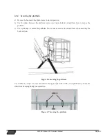
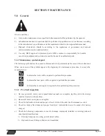
Page 50: ...secure the platform c Use nylon tape to secure the platform Do not use excessive downward force when securing the boom section Figure 4 6 Securing the platform Use a cable tie or rope to secure the sl...

Page 51: ...e or more of the symbols appear at the beginning of a maintenance procedure it conveys the meaning below Indicates that tools will be required to perform this procedure Indicates that new parts will b...

Page 52: ...ways relieve hydraulic pressure from all hydraulic circuits before loosening or removing hydraulic components e Do not use your hand to check for leaks Use a piece of card board or paper to search for...

Page 53: ...um scale Add oil as needed Do not overfill Hydraulic oil capacity Table 5 1 Capacity Model Hydraulic tank 75L 19 8 us gal Hydraulic system oil quality tank included 123KG 271 lb RRP LIW 2SHUDWRU V 0DQ...

Page 54: ...re limit Under normal conditions the recommended oil temperature should be controlled at 30 86 to 60 140 The oil temperature affects the oil viscosity and the thickness of the oil film High temperatur...

Page 55: ...l manufacturer or qualified third party testing agency for analysis and to determine whether it is still usable Changing oil return filter The oil return filter element is recommended to be changed ev...

Page 56: ...ng terminal protectors and a corrosion preventative sealant will help eliminate the corrosion on the battery terminals and cables 5 4 Regular Maintenance Maintenance performed quarterly annually and e...

Page 57: ...pletely lubricated Do not over lubricate the bearings otherwise it will cause damage to outside seal of casing b Hydraulic tank DFWRU ILOO KHYURQ Liquid Level 50 62 L 13 2 16 4 us gal Interval Check l...

Page 58: ...months or 300 hrs Hydraulic Tank Breather Maintenance Point s Tank Breather Interval Change after first 50 hrs and every 6 months or 300 hrs thereafter Comment Remove wing nut and cover to replace Un...

Page 59: ...ing characteristics a Equal or greater ply load rating and size of original b Tire tread contact width equal or greater than original c Wheel diameter width and offset dimensions equal to the original...

Page 60: ...re to use only the nuts matched to the cone angle of the wheel Tighten the lug nuts to the proper torque to prevent wheels from coming loose Use a torque wrench to tighten the fasteners If you do not...

Page 61: ...que Table 5 3 Wheel Torque Table Torque Sequence 1st Stage 2nd Stage 3rd Stage 75 Nm 54 3 ft lb 150Nm 108 5 ft lb 275 Nm 198 9 ft lb d Wheel nuts should be torqued after first 50 hours of operation an...

Page 62: ...RI GDPDJH GLVWRUWLRQ DQG H FHVVLYH ZHDU DEOHV KRVHV DUH SURSHUO URXWHG QR FKDILQJ RU OHDNV QVSHFW DOO F OLQGHU SLQV SLYRW SLQV DWWDFKLQJ DQG UHWHQWLRQ KDUGZDUH IRU GDP DJH GLVWRUWLRQ DQG H FHVVLYH ZHD...

Page 63: ...1155 Dtc_Incline_Sensor_Comm_Erro 11156 Dtc_Incline_Sensor_Not_Standardization 13157 Dtc_Boom_Angle_Sensor_Out_Of_Range 13158 Dtc_Boom_Angle_Sensor_Comm_Error 13159 Dtc_Boom_Angle_Sensor_Not_Standardi...

Page 64: ...4379 Dtc_Fault_Pm_Main_Lift_Joystick_Dn_Limit 24380 Dtc_Fault_Pm_Main_Lift_Joystick_Medium_Offset 24381 Dtc_Fault_Pm_Drive_Joystick_Up_Limit 24382 Dtc_Fault_Pm_Drive_Joystick_Dn_Limit 24383 Dtc_Fault_...

Page 65: ..._Valve_Short_To_Ground 22583 Dtc_Function_Unload_Valve_Short_To_Power 22584 Dtc_Function_Unload_Valve_Open_Circuit 22585 Dtc_4select_Main_Control_Left_Valve_Short_To_Ground 22586 Dtc_4select_Main_Cont...

Page 66: ...fe_Valve_Open_Circuit 23620 Dtc_Tower_Lift_Dn_Speed_Valve_Short_To_Ground 23621 Dtc_Tower_Lift_Dn_Speed_Valve_Short_To_Power 23622 Dtc_Tower_Lift_Dn_Speed_Valve_Open_Circuit Driver 1018 Dtc_Controller...

Page 67: ...Dtc_Os_General_1 1114 Dtc_Pdo_Timeout_1 1115 Dtc_Stall_Detected_1 1116 Dtc_Fault_On_Other_Traction_Controller_1 1117 Dtc_Dual_Severe_Fault_1 1119 Dtc_Supervisor_Fault_1 1120 Dtc_Supervisor_Incompatibl...

Page 68: ...n_Short_2 2054 Dtc_Encoder_Fault_2 2055 Dtc_Motor_Open_2 2056 Dtc_Main_Contactor_Welded_2 2057 Dtc_Main_Contactor_Did_Not_Close_2 2065 Dtc_Throttle_Wiper_High_2 2066 Dtc_Throttle_Wiper_Low_2 2067 Dtc_...

Page 69: ...dervoltage_3 3024 Dtc_Severe_Overvoltage_3 3034 Dtc_Controller_Overtemp_Cutback_3 3035 Dtc_Undervoltage_Cutback_3 3036 Dtc_Overvoltage_Cutback_3 3037 Dtc_Supply_5v_Failure_3 3038 Dtc_Do6_Open_Or_Short...

Page 70: ...3136 Dtc_Encoder_Pulse_Error_3 3137 Dtc_Motor_Type_Fault_3 3145 Dtc_Vcl_Os_Mismatch_3 3146 Dtc_Em_Brake_Failed_To_Set_3 3147 Dtc_Encoder_Los_3 3148 Dtc_Emr_Rev_Timeout_3 3152 Dtc_Illegal_Model_Number_...

Page 71: ...Dtc_Pot_Low_Overcurrent_4 4070 Dtc_Eeprom_Failure_4 4071 Dtc_Hpd_Sequencing_Fault_4 4073 Dtc_Parameter_Change_Fault_4 4104 Dtc_Vcl_Run_Time_Error_4 4105 Dtc_External_Supply_Out_Of_Range_4 4113 Dtc_Os...

Page 72: ..._Motor_Temp_Hot_Cutback_5 5041 Dtc_Motor_Temp_Sensor_Fault_5 5049 Dtc_Main_Open_Short_5 5050 Dtc_Embrake_Open_Short_5 5051 Dtc_Coil3_Driver_Open_Short_5 5052 Dtc_Coil4_Driver_Open_Short_5 5053 Dtc_Pd_...

Page 73: ...ult_5 5119 Dtc_Supervisor_Fault_5 5120 Dtc_Supervisor_Incompatible_5 5135 Dtc_Motor_Characterization_Fault_5 5136 Dtc_Encoder_Pulse_Error_5 5137 Dtc_Motor_Type_Fault_5 5145 Dtc_Vcl_Os_Mismatch_5 5146...

Page 74: ...y for short term 2 Ex factory Test Items Machine must complete testing items in the following table before delivery Table 1 Testing items before delivery Tests Items Load Testing Testing Movement Over...

Page 75: ...RRP LIW 2SHUDWRU V 0DQXDO 1RWHV...

Page 76: ...3428 Bullock Lane San Luis Obispo CA 93401 USA Tel USA 1 805 303 2066 Toll Free USA Canada 800 303 0499 www goGMG com 2 0 1 5 5283 1...

Reviews: