background image


D6031 

- SIL 3 Switch/Proximity Detector Repeater Open Collector Output 

G.M. International ISM0214-2 

ON 


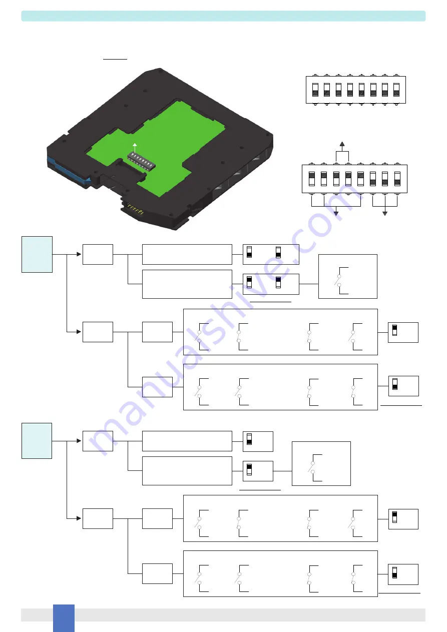
Configuration 

Dip switch configuration 

1

2

3

4

CH1

5

6

7

8

CH2

ON

Must be set to 

"OFF" position

D6031D used as double channel 

A configuration DIP switch is located on component side of pcb. This switch allows the configuration of input/output relationship, fault detection functions and operating mode. 


WARNING:

 dip-switch 6-7-8 must be set to “OFF” position. 

Input Input 

Output 

Input 

Output 

Input 

CH1 

Setting 

Line fault 
detection 

IN / OUT 

Operation 

NO-NC or 

NC-NO 

NO-NO or 

NC-NC 

Disabled 

(switch / proximity sensor) 

Enabled 

(proximity sensor or switch 

with end of line resistors, de-energizes 

transistor in fault condition) 


NO 

OR 

NC 


NO 

OR 

NC 

1


OFF 

5

OFF 

1

ON 

5

ON 


NC 

NO 

Output 

NO 

Output 

NC 

Position in fault condition 

2

ON 

2

OFF 

Input Input 

Output 

Input 

Output 

Input 

CH2 

Setting 

Line fault 
detection 

IN / OUT 

Operation 

NO-NC or 

NC-NO 

NO-NO or 

NC-NC 

Disabled 

(switch / proximity sensor) 

Enabled 

(proximity sensor or switch 

with end of line resistors, de-energizes 

transistor in fault condition) 


NO 

10 

OR 

NC 

10 


NO 

10 

OR 

NC 

10 

NC 

NO 

Output 

NO 

Output 

NC 

3

3

ON 

OFF 

Position in fault condition 

4

4

ON 

OFF 

1

2

3

4

5

6

7

8

ON

Dip switch factory settings. All Switches are OFF 

For SIL Application 

For SIL Application 

For SIL Application 

For SIL Application 

Summary of Contents for D6031D

Page 1: ...y Detector Repeater Open Collector Output G M International ISM0214 2 SIL 3 Switch Proximity Detector Repeater Transistor Open Collector Output DIN Rail and Termination Board Models D6031S D6031D D6031S D6031D INSTRUCTION MANUAL ...

Page 2: ...lly protected Current consumption 24 V 22 mA for 2 channels D6031D 12 mA for 1 channel D6031S with short circuit input and transistor closed typical Power dissipation 0 53 W for 2 channels D6031D 0 30 W for 1 channel D6031S with 24 V supply voltage short circuit input and transistor closed typical Isolation Test Voltage In Out 2 5 KV In Supply 2 5 KV In In 500 V Out Supply 500 V Out Out 500 V Inpu...

Page 3: ...t detection Three port isolation Input Output Supply EMC Compatibility to EN61000 6 2 EN61000 6 4 EN61326 1 EN61326 3 1 for safety system In field programmability by DIP Switch TÜV Certification TÜV Functional Safety Certification High Density two channels per unit Simplified installation using standard DIN Rail and plug in terminal blocks with or without Power Bus or customized Termination Boards...

Page 4: ... D5031D Duplicator and Fault Out 5 6 1 2 Out 1 Signal SIL 3 7 8 Termination board connector Supply 24 Vdc Power and Fault Bus F 3 4 Out 2 Duplicator or Fault 9 10 In Proximity voltage free Contact voltage free Contact R1 R2 Resistors R1 R2 used with voltage free contact required for line fault detection Terminals 9 10 must be shorted to set module as Duplicator or Fault Out MODEL D5031S 6 1 2 Out ...

Page 5: ...in a plastic enclosure suitable for installation on T35 DIN Rail according to EN50022 with or without Power Bus or on customized Termination Board D6031 unit can be mounted with any orientation over the entire ambient temperature range Electrical connection of conductors up to 2 5 mm are accommodated by polarized plug in removable screw terminal blocks which can be plugged in out into a powered un...

Page 6: ...ity sensor Enabled proximity sensor or switch with end of line resistors de energizes transistor in fault condition 7 NO 8 OR NC 7 8 7 NO 8 OR NC 7 8 1 OFF 5 OFF 1 ON 5 ON NC 1 2 1 NO 2 Output 1 NO 2 Output NC 1 2 Position in fault condition 1 2 2 ON 2 OFF Input Input Output Input Output Input CH2 Setting Line fault detection IN OUT Operation NO NC or NC NO NO NO or NC NC Disabled switch proximity...

Page 7: ...C Mode ON OFF OFF ON Disabled switch proximity sensor Enabled proximity sensor or switch with end of line resistors de energizes transistor in fault condition No Fault No Fault 1 OFF 5 OFF 5 ON Output 2 Operation Input Input Output 1 Input Output 1 Input 7 NO 8 OR NC 7 8 7 NO 8 OR NC 7 8 NC 1 2 1 NO 2 Output 1 1 NO 2 Output 1 NC 1 2 NC 3 4 3 NO 4 Set SW4 equal to SW2 Set SW4 opposite to SW2 6 6 ON...

Page 8: ...on 1 2 3 4 7 8 must be set to OFF position 3 4 6 Not used 5 6 7 8 ON CH Setting Line fault detection IN OUT Operation NO NC or NC NO NO NO or NC NC Disabled switch proximity sensor Enabled proximity sensor or switch with end of line resistors de energizes transistor in fault condition 1 OFF 5 OFF 1 ON 5 ON Input Input Output Input Output Input 7 NO 8 OR NC 7 8 7 NO 8 OR NC 7 8 NC 1 2 1 NO 2 Output...

Page 9: ...n fault condition for SIL application if line fault detection enabled SW1 ON ON OFF ON Parallel for SIL applica tion Set equal to SW2 Not specified Fault condition OFF Reverse Set opposite to SW2 OFF for SIL application ON OFF NO ON NC for SIL applica tion OFF Fault Output D6031D used as double channel Configuration Summary Table WARNING dip switch 6 7 8 must be set to OFF position D6031D used as ...

Reviews: