GS-Series Drafting Tables ASSEMBLY INSTRUCTIONS
TOOLS REQUIRED FOR ASSEMBLY
Cordless Hand Drill with Phillips Head Bit
or Phillips Screw Driver
BEFORE ASSEMBLING THE WORKBENCH
Read through the assembly instructions to familiarize
yourself with the order in which the parts are assembled.
We suggest that you clear & vacuum the area where the
bench is to be assembled. It is important that the bench
is assembled in the same sequence as instructed.
S
TEP 1
S
TEP 2
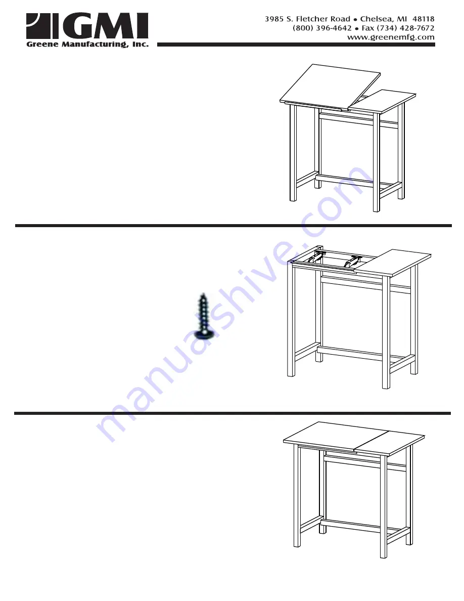
Set the reference top on the base.
Adjust the top to leave a 1-1/2"
overhang in the front & 1" overhang
on the right side.
Attach the top to the support braces in
4 places using #10 x 5/8” SPAX screws.
Reference Area Option
For tables without reference area skip step (1).
Set the drafting top on the base. If your station has
a reference top align the fronts of the 2 tops. Be
sure to keep an even gap between the 2 tops ( 1/16" - 1/8").
For tables without reference top, center drafting top over frame
overhang on both the left and right hand sides. Allow an 1-1/2”
overhang in the front.
Attach the top to the hinge using four #8 x 5/8"
screws.
Attach the top to the ratchet lifts using four
#8 x 5/8" screws. Be sure the top is resting flat on the table frame
and the ratchet lifts are perpendicular to the tube frame.
Shown with optional reference area.
Shown with optional reference area.
Shown with optional reference area.
For tables without reference area skip step (1).


