background image

How to laminate

1. How to load film

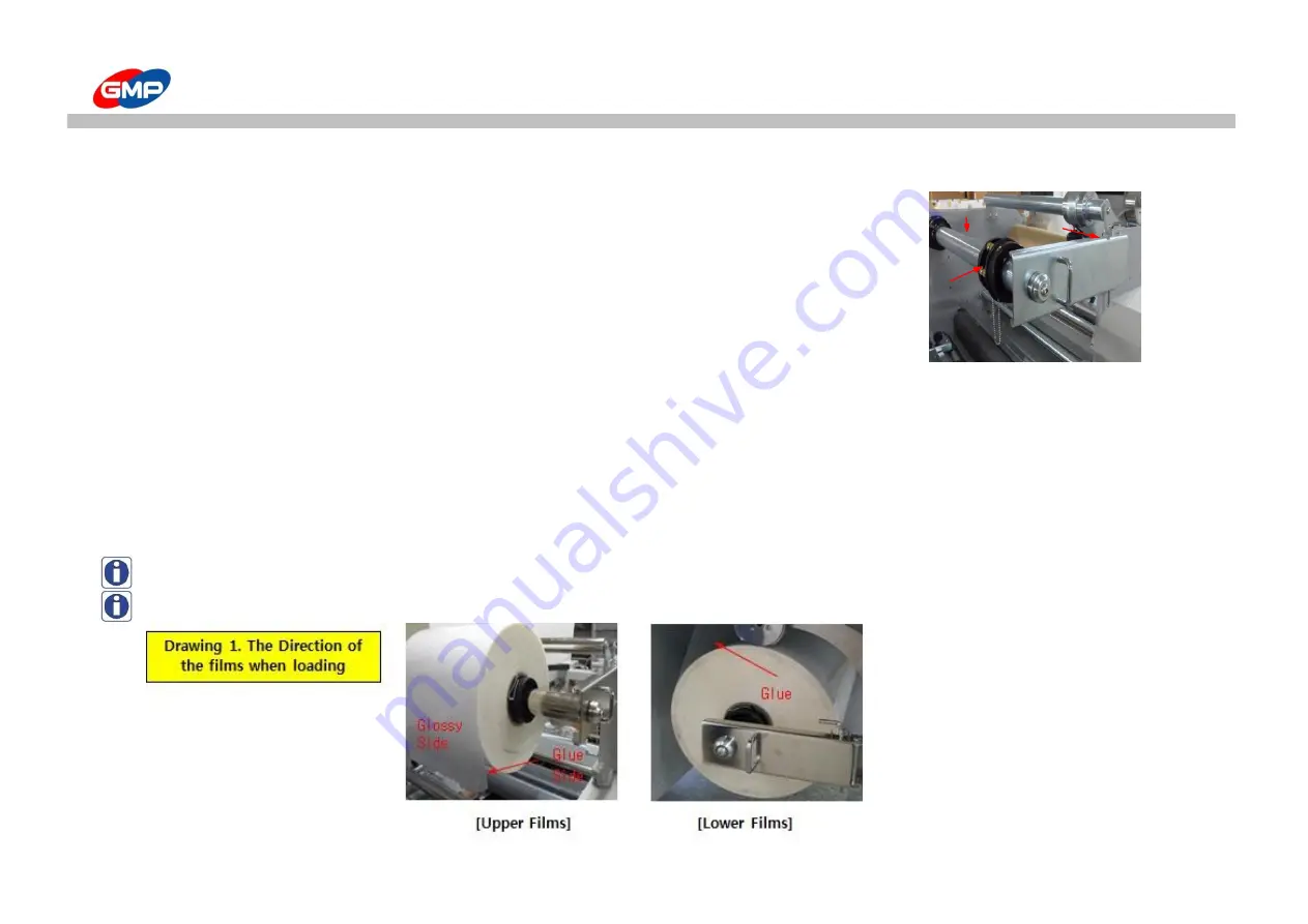
☞ Composition of Film installing devices

① Film Shaft : The film shaft is used to load a laminating roll films.

② Film Shaft Holder Fixing Pin. : Film Shaft Holder Fixing Pin is used to fix the Film shaft Holder.

③ Film Shaft Holder : The Film Shaft Holder is used to prevent the Film Shaft from moving

④ Film Core : Film Core is used to fix the laminating roll films.

※ How to install film

① Remove the Film Shaft Holder Fixing Pin and pull the Film Shaft Holder

② remove any side of Film Core by using the Film Shaft Holder Fixing Pin

③ Insert or Remove film roll into or from Film Shaft. (Please refer to the Drawing 1)

④ Insert a film roll into the film shaft after the holder fixing pin is removed.

⑤ Tighten the Film core fixing bolt after film is loaded.

Remarks

 : When doing 

"Single side lamination"

 please use 5~10mm narrower width films than substrate to prevent the contamination of cutting error

Remarks

 : When doing 

"Double side lamination"

 Please use the same width for the upper and lower films to to prevent the contamination on roller.


37/60

Summary of Contents for PROTOPIC AUTO-540 HS

Page 1: ...PROTOPIC AUTO 540 QUATRO SLIT Before operating the unit please read this manual thoroughly and retain it for future reference The design specification of the machine could be changed for improvement w...

Page 2: ...s 9 page Move Installation 10 page DIGITAL SLEEKING SOLUTION Introduction of DIGITAL SLEEKING 49 page HOW TO USE CONTROL PANEL GLOSS MATT SLEEKING 50 page Details for Display 13 page HOLOGRAM SLEEKING...

Page 3: ...l injury and damage the machine This symbol means a required action If you don t follow this action your safety is not guaranteed Required action will be included in this symbol Reference The sign abo...

Page 4: ...power and voltage It can be a reason of fireflame or an electricity fireflame Do not dissemble make repairs or convert the machine Contact your dealer for repairs Ensure all hair neckties necklaces ar...

Page 5: ...Do not touch the roller with your hand as you could be burnt Please avoid installing near the following places Gas stove Ventilator or Air conditioner due the higher temperature or higher humidity Do...

Page 6: ...motor rollers rotation and system operation In case of emergency use this switch How to use Press the Red button to operate the Emgency Stop Switch All system is stopped when this is pressed Turn the...

Page 7: ...d be burnt Do not touch on the heating part Roller s higher temperature and press can damage your body Electricity Caution Cutting Caution Inside the machine high voltage flows Do not touch your body...

Page 8: ...1 PAPER GUIDE 2 AIR COMPRESSOR 1 AIR HOSE 1 GLASS TUBE FUSE 20mm 250V 12 5A 4 GLASS TUBE FUSE 20mm 250V 15A 2 WRENCH SET 1 LAMI TABLE 1 MANUAL 1 SEPARATOR IDLE ROLLER 1 LEADING PAPER 1 WASTE GUIDE 2 W...

Page 9: ...Knob Feeder Roller Pressure Gauge Knob Control Panel Uppper Film Tension Adjustmen Knob Feeding Table Lower Film Tension Adjustment Knob Side Slitter Film Shaft Support E Stop S W Film Rewinder Waste...

Page 10: ...es to move it by caster wheel 1 If a distance to move the laminator is less than 10m distance in the same area 2 Move the laminator gently with more than 4 persons at least During it is moved grap eac...

Page 11: ...different depends on the job circumstance Power Connection AC 220 240V 15A Independent Power System WARNING It must be grounded for safety Otherwise this could be a cause of trouble and electric shoc...

Page 12: ...if you place inside of Lamitable the high temperature could cause malfunction or trouble Maintenance of Compressor A large amount of moisture is made during the air compressor is operated Then the dr...

Page 13: ...emp operation for Polynex Film set temp 120 FOIL L Low Temp operation for Metallic Foil set temp 115 Nylon Job with Nylonex Film set temp 130 FOIL H High Temp operation for Metallic Foil set temp 125...

Page 14: ...et bursting time SPEED for display of roller speed To display rotation speed of laminating roller Speed setting range is Min 1 Max 15 NOTE Start at low speed for initial stage of job LENGTH for displa...

Page 15: ...ation status of SHUTTER Press TABLE UP button to operate it manually WHEEL Display operation status of WHEEL Press TABLE DOWN button to operate it manually FD Display operation status of FEEDER MOTOR...

Page 16: ...OR OFF Press MANUAL RUN button to operate MISFEEDING SENSOR manually SO SENSOR OFF ON status if the SENSOR detect system is not stopped SO SENSOR OFF OFF status if the SENSOR detect system is stopped...

Page 17: ...ength Setting Range is Min 250 Max 800 NOTE How to set substrate length is the same as how to set speed in SPEED menu It saves automatically 5 seconds after set up NOTE The laminator has Underlap Cutt...

Page 18: ...s DAILY COUNTER is reset When the LED is on top temp control is available On status of LED ON if temp button is pressed you can control bottom temperature NOTE How to set substrate Temp is the same as...

Page 19: ...n to laminate NYLONEX Nylon base PERFEX PET base films TABLE UP DOWN To make the Feeding Table UP or DOWN If the DOWN is selected the feeding table goes down and while the UP is pressed the feeding ta...

Page 20: ...he lamination is stopped the vacuum pump is in operation ON status and if it is pressed again it turns to stop the Vacuum Pump FEEDER HOME To place the Feeder Motor at Origin Point Feeder Origin Point...

Page 21: ...e loading sensor STOP Press STOP button to disengage roller and rotation of roller feeder operation are stopped In accordance with Feeder Motor origin point status the system is stopped as follows the...

Page 22: ...ure would be blinking for every 0 5 sec till it would be recovered To display Alarm for Main Motor Drive If input output voltage is not be at the Motor Drive or encoder for motor control is defective...

Page 23: ...release from alarm press STOP button for 1 sec on SUB2 Mode To display Error for TBL UP LIMIT DETECT When the Table Up limit S W is ON if RUN button is pressed the alarm message is displayed for 3 se...

Page 24: ...e alarm message for 3 secs Error for Feeder E Stop Please check the Feeder E Stop button E stop and Safety Cover is opened Please check the E stop Safety Cover and Burst Safety Cover Table Up Limit is...

Page 25: ...rs are passed from the measured time the machine is in STAND BY mode In the STAND BY mode message of STAND BY STATUS is blinking on LCD PANEL Release from STAND BY mode Press RUN button in STAND BY mo...

Page 26: ...pressure would be too high this could be a cause of feeding error BLAST FOOT To blow air between picked sheet and stacked sheets to make easy to feed sheet to the feeding wheel Adjust the feeder posi...

Page 27: ...ix it NOTE If the Feeder would not be fixed this could be a cause of damage on the feeder while lamination Feeder Height Adjustment Knob Adjust the Feeder height position If the feeding table would be...

Page 28: ...eding wheel Ex If a pressure on right feeding wheel is higher substrates will be moved to the left to the laminating roller In this above case loosen the right wheel fixing bolt Substrate Stopper To m...

Page 29: ...ist trouble in feeding alignment process Adjust position of guide for substrate size and stack substrates Feeding Table To pile up substrates for lamination Min substrate size for stacking is W 210mm...

Page 30: ...OTE Different film or different substrate requires different pressure The recommendable max pressure is less than 0 6MPa 6 Switch to engage the Embossing Roller To engage or disengage the Embossing Ro...

Page 31: ...ion This is not caused by the trouble in the Laminator Decurling Device is to avoid the Curling on the Laminated Results after single side lamination Adjust the Decurling Status with the Handle as the...

Page 32: ...nation to check its pressure is in optimum level Feeding Lamp To let operator know the time to put a substrate on feeder When the lamp is ON put a substrate on the feeder table Feeder makes distance o...

Page 33: ...ration could make conveyor belt loosen If the belt is loosen feeding could not be working properly Adjust its tension with Tension Adjustment Bolts that are at Feed Table Turn it to the right to incre...

Page 34: ...n the device from the film ends by 1 3mm inside To make clear holes on films with adjust perforator height adjustment bolt WARNING In the initial loading status if the perforator is needed to be moved...

Page 35: ...applications It has 5Cm 2EA 10Cm 1EA 20Cm 1EA and refer to the below for its move installation SLIT MODULE FIXING BOLT to fix the SLIT MODULE This is for installation de installation of SLIT MODULE a...

Page 36: ...If it would be occurred for more than 2 times continuously please ask to the supplier Tray Table The Tray Table is useful for easy arrangement of Laminated Results Adjust the Guides on the Table for S...

Page 37: ...Holder Fixing Pin and pull the Film Shaft Holder remove any side of Film Core by using the Film Shaft Holder Fixing Pin Insert or Remove film roll into or from Film Shaft Please refer to the Drawing...

Page 38: ...table Positioning example if the substrate width is 480mm and film witdh is 470mm The Paper Alignment Guide should be positioned on 5mm of inner side than Paper Guide Slit knife Position You can relo...

Page 39: ...loading paper 2 Loading bottom film Pass the Leading paper by following the below picture stick it with bottom film and tape is with loading paper 3 Loading Upper film Pass the upper film through the...

Page 40: ...ktie necklace long raced or that kind of clothes These could be wound in the driving device and will be a cause of fatal injury Checking Points for Test Lamination 1 Distance of Overlap for Substrates...

Page 41: ...op lamination could make a mark on a laminated results 2 Basically thicker substrates requires lower speed or higher temp 3 Thinner substrates requires higher speed or lower temp 4 For perfect laminat...

Page 42: ...How to laminate Web diagrams 42 60...

Page 43: ...aution When cleansing the roller use isoprophilene alcohol only Caution after lamination the laminating roller temp is too high if it would be contacted to body this could be a cause of burn Main Body...

Page 44: ...are not fed 1 If both ends of sustrate has big curl and they contact to feeder 1 Make the paper flat 2 If substrate is on less than 2 conveyor belt 2 Substrate must be on the more than 3 conveyor bel...

Page 45: ...ssure is not stable 3 Please ask to a supplier 4 If paper width is too much wider than film width by more than 30mm 4 Place a film at 3 5mm inside from the substrate end Curling on laminated results 1...

Page 46: ...ade height with adjustment bolt not good Refer to the Perforator Adjustment 2 If Bursting Roller Pressure is lower 2 Adjust its height with Bursting Roller Height Adjustment Handle Refer to the Bursti...

Page 47: ...ask to a supplier 2 If foreign substances are 2 Please remove the foreign substances in between the sensor and laminating roller 3 if the heater is defective 3 Please ask to a supplier 4 If the THERM...

Page 48: ...minating Film POLYNEX PERFEX NYLONEX FILM 20 44 Rated Voltage AC 220 240V 15A Power Consumption 3 5 kw Warm up Time 7 mins Heating System DUAL INFRARED HEATER Roller Temperature MAX 150 Temp Control J...

Page 49: ...FINISH SLEEKING FOIL GLOSS SLEEKING FOIL MATT SLEEKING FOIL 2 HOLOGRAM HOLOGRAM SLEEKING FILM SPARKLE HOLOGRAM HIPER PLAID HOLOGRAM CRYSTAL HOLOGRAM MILKY WAY HOLOGRAM STAR HOLOGRAM SPECTRUM HOLOGRAM...

Page 50: ...del Speed Set Temp Pressure MPa Protopic series 3 110 0 5 Table 1 1 Picture 1 1 How to load the Foils Picture 1 2 Note Please be informed that in order to realize the sleeking effects such as Whole Gl...

Page 51: ...POD Prints DIGITAL PRINT FILM LAMINATOR Film Loading SLEEKING FINISH 2 Whole Page Gloss Matt SLEEKING SOLUTION 1 Print Out POD Prints 2 Load GLOSS MATT SLEEKING FOIL as the above picture 3 Setting Rol...

Page 52: ...D Prints DIGITAL PRINT POD Prints DIGITAL PRINT SLEEKING FINISH OFFSET Prints 1 Cut the Car Image Picture 1 2 with Image Editing Program 3 Print the Background Image 6 Only the Spot Image has Sleeking...

Page 53: ...D SLEEKING FINISH OFFSET Prints 1 Cut the Car Image Picture 1 2 with Image Editing Program 2 Print out the Background Image only 3 Laminate in GMP Laminator with GMP Sleeking Foil 4 Print the Spot Ima...

Page 54: ...Protopic series 3 105 0 5 HIPER PLAID HOLOGRAM CRYSTAL HOLOGRAM Table 2 1 MILKY WAY HOLOGRAM STAR HOLOGRAM SPECTRUM HOLOGRAM How to load the Foils MOSAIC HOLOGRAM Picture 2 1 Picture 2 2 Note Please...

Page 55: ...ints DIGITAL PRINT FILM LAMINATOR Foil Loading SLEEKING FINISH 2 Whole Page HOLOGRAM SLEEKING SOLUTION 1 Print out the POD prints 2 Load the GLOSS SLEEKING FOIL as the above picture 3 Setting with Rol...

Page 56: ...5252 POD Prints DIGITAL PRINT POD Prints SLEEKING FINISH OFFSET Table 2 3 Spot Hologram Sleeking 2 Spot HOLOGRAM SLEEKING SOLUTION 1 Cut the Carrot Image Picture 2 1 with Image Editing Program 3 Print...

Page 57: ...SLEEKING FINISH OFFSET Prints Table 2 4 Spot Hologram Sleeking with Lamination 3 Spot HOLOGRAM SLEEKING SOLUTION with Lamination 1 Cut the Carrot Image Picture 2 1 with Image Editing Program 2 Print...

Page 58: ...e MPa SILVER Protopic series 3 110 0 5 Table 3 1 Picture 3 1 How to load the Foils Picture 3 2 Note Please be informed that in order to realize the sleeking effects such as Whole Gloss Matt sleeking S...

Page 59: ...RINT POD Prints DIGITAL PRINT SLEEKING FINISH OFFSET Prints Table 3 3 Spot Gold Silver Metallic Sleeking 2 Spot METALLIC SLEEKING 5 Only Spot Image has the Sleeking Effect 1 Cut the Spot Image Picture...

Page 60: ...STAR MOSAIC SPARKLE HYPER PLAID HOLOGRAM SLEEKING FOIL PET12 77CORE 1000M HOLOGRAM SLEEKING FOIL PET25 77CORE 1000M HOLOGRAM SLEEKING FOIL PET50 77CORE 1000M HOLOGRAM FOIL UV20 77CORE 1000M HOLOGRAM...

Reviews: