background image

1 0991 483


EN


21.12.2011 


NGV A3 

VALVE 

M

ANUAL


I

NSTALLATION

, U

SE AND 

M

AINTENANCE


43 / 46


1.05 

ENG 


6.4.1 TROUBLESHOOTING 


Fault 

Possible cause 

Possible solution 


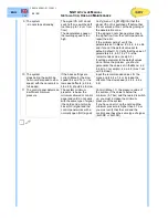
1  The system 

- do not start but the pump 
works 

The card do not receive the 
signal VS from the control 
panel. 
The control panel do not 
receive/recognize the RUN 
signal from the card. 

Verify in the Menu 1.4 if the card receive 
the signal VS from control panel. Verfy that 
signals RDY and RUN are according to the 
schema 2.3.3 


2  The system 

- run slowly in up and down 
direction 
- stops immediately without 
deceleration 

The Menu 5.12 is set on 
“Install” and the system run 
only in inspection speed. 

The default parameter is “Install”. At the 
end of the installation you must set the 
parameter 5.12 = “Normal” 


3  The system 

- run only with low speed 

The card 
- do not receive the speed 
signal (V0, V1, V2) 
- receive the speed signal 
after the direction signal (VS, 
D) 

Verify (menu 1.4 S0123DICA) that the card 
receives the speed and the direction 
signals. 
If the card do not receives any signal check 
the signal flow from the control panel and 
repair the error. 


4  The system 

- has an abrupt departure in 
up direction (run fast for 
piece of the travel, slows, 
and return to the correct 
speed. 

The motor starts before of 
the RUN signal 

Verify that the signals RUN and RDY are in 
compliance with § 2.3.3. Verify  (menù 1.4 
S0123DICA) that all signals are received 
and (menù 1.5 1234YND) send correctly 
to/from the card. 
The motor do not must start before: 
- VS, up command 
- RUN 
- Out 4=UP if used 


5  The system 

- starts in up direction with 
an not regular acceleration 
(it starts with a little burst 
and immediately return to 
the correct acceleration) 

The starting time is not 
correct, the oil output line 
was open in advance and 
the oil reach the piston until 
the motor is at full. 

Increase the value of the menu point 6.8 to 
delay the oil output line opening. 


6  The system 

- run irregularly and 
inaccurate 

The basic parameters are 
not corrects 

Verify (menu 5) that the values set are in 
compliance with the effective system data. 
Particularly, verify values 5.5 Pstat MIN e 
5.6 Pstat MAX 


7  The system 

- stops over/under the 
landing level when the 
system has a reduced floor 
distance (< 1,8m) 

The system arrive at landing 
in nominal speed (Vo) 
instead of intermediate 
speed V1. 
The intermediate speed set 
is too high 

Verify that the card receives the speed 
signal V1 (menu 1.4 S0123DICA). If the 
card do not receive the signal check the 
signal flow from the control panel and 
repair the error. 
If the card receive the signal you must 
decrease the intermediate speed V1 
parameter (in up direction menu 6.2, in 
down direction menu 7.2 recommended 
value 0,3 m/s) and/or increase the 
deceleration distance. 


8  The system 

- do not decelerate correctly 

The speed signals (V0, V1 o 
V2) are not according with § 
3.5 or the magnet position is 
not correct 

Verify (menù 1.4 S0123DICA) that the 
status of the speed signal V0 changes from 
1 to 0 when the car comes in the 
deceleration zone. 
Verify that the parameters 4.9, 4.10, 4.11 e 
4.12 are correctly set (default = 0) and 
otherwise, set the correct value. 
Verify that the magnets are at the correct 
distance from the floor 
If the problem persist, please, contact the 
technical support. 

Summary of Contents for NGV A3

Page 1: ...CS EQUIPMENTS AND COMPONENTS FOR LIFTS UNI EN ISO 9001 Certified Company 1 05 ENG English NGV A3 VALVE NGV A3 VALVE MANUAL INSTALLATION USE AND MAINTENANACE 1 0991 483 EN AVAILABLE WITH TANK TYPE GL F1 T2 T3 T4 MRL T MRL H ...

Page 2: ... 5 2 CONNECTION SCHEMAS FOR SIGNALS 15 2 5 3 CONNECTION SCHEMAS FOR POWER 15 2 6 CONNECTIONS TO THE TERMINAL 16 2 7 CONNECTIONS TO THE CARD 16 2 8 CONNECTION OF HYDRAULIC PIPES 17 2 8 1 CONNECTION WITH FLEXIBLE HOSE 17 2 8 2 CONNECTION WITH A RIGID PIPE 17 3 NGV A3 CONTROL BOARD 18 3 1 ELECTRICAL FEATURES 18 3 2 PERFORMANCES 18 3 2 1 SIGNALLERS 18 3 3 CONNECTIONS 19 3 3 1 CONTROL PANEL INTERFACE 1...

Page 3: ...ENSORS 45 6 5 1 SENSOR S1 45 6 5 2 SENSOR S2 45 6 5 3 SENSOR S3 45 7 CERTIFICATES 46 ENG All rights reserved Any kind of exploitation in any form and by any means is forbidden without a written permission of GMV Spa GMV Spa within technical or manufacturing progress reserves the right to modify parts or this manual without notice Drawings descriptions and data included in this manual are indicativ...

Page 4: ...MP Motor pump MPS Maximum pressure spool NGV A3 NGV A3 Valve Complete OFF Not powered ON Powered OPP MPS pilot valve P VRP pilot spool PAM Hand pump PT Pressure transducer RDY Ready Ready signal card output to control panel RO Oil heating resistance RT Motor thermistors RUN Run Start signal card output to control panel S1 VRP Sensor to control the VRP closing S2 VBC Sensor to control the VB closin...

Page 5: ... for the construction and installation of lifts EN 1050 Safety of machinery Principles for risk assessment ISO 3864 Safety colours and safety signs 0 2 DOCUMENTS RELATED WITH INSTALLATION The documents to use for the installation are those required by the EN81 2 1998 and by the rules in force particularly the following THIS INSTALLATION MANUAL WIRING AND HYDRAULIC DIAGRAMS EN81 2 1998 16 2 A 6 AND...

Page 6: ...maintenance of the installation shall be carried out to ensure the reliability of the installation The access and the associated environment shall be maintained in good working order The competence of the maintenance person within the maintenance organization shall be continuously updated NOTE We inform the owner of the installation that the qualification of the maintenance organization needs to b...

Page 7: ...e comfort comparable to a VVVF electric and no consumption in standby mode Maintenance speed adjustable Maximum value reached under optimal conditions and in combination with other products GMV The driving option INTERNAL FEED BACK CAR LOAD TEMPERATURE The choice to immediate savings interfaced with all existing and new systems Not require encoder reduce consumption up to 20 The valve stored the o...

Page 8: ...tead it opens the oil way to the valve block chamber C2 Its opening is made by the pushing of the piston P that is opened by the pilot operated valve VMD Spool VB It s the main part of the control block It adjusts the oil quantity that should be discharged and determines all the movements of the car Its movement is controlled by a stepping motor coupled to the spool VB through a screw nut coupling...

Page 9: ...B spool To a more opening of the spool corresponds an higher speed of the car The phase of arrival at the landing is determined by the following events The VRP spool is opened by the push of the spools P controlled by the VMD pilot valve The VB spool closes to stop the car The VMD valve raised the landing is de energized and consequently the VRP spool closes During standard operation of the system...

Page 10: ... never exclude the safety devices and never connect the motor pump directly to the power supply 2 1 HYDRAULIC CONNECTIONS 2 1 1 MINIMUM DIMENSIONS AND HOLES FOR POWER UNIT 135 113 83 52 131 18 14 105 137 15 10 15 57 Ø9 x 4 fori 35 61 5 Ø28 M6 M6 16 5 41 5 19 24 48 74 1 1 4 G IN 1 1 4 G OUT 11 5 54 5 43 5 77 5 6 6 310 340 393 310 400 1 1 4 IN 1 1 4 OUT ...

Page 11: ... 11 46 1 05 ENG 2 1 2 INPUT AND OUTPUT POWER UNIT SIDE 1 1 4 OUT M8 OUT 1 1 4 IN M8 OUT M8 OUT M8 OUT M8 OUT 3 4 OUT 12x8 PAM PAM 12x8 IN 1 OUT 1 OUT OUT M8 2 2 HYDRAULIC CIRCUIT M VS1 VB VR1 VR ML VSMA PAM VR2 VS2 VC 3006 B ISP MAN PT 4 2 1 5 3 SM TT VAL CARD J NGV A3 VRP K VMD ...

Page 12: ...DY output should not send commando to the valve and or the motor pump In FAULT condition the motor pump group should NOT be active WARNING To detect the unintended movement of the car the system use the circuit required by paragraph 7 7 1 and 14 2 1 2 of the rule EN 81 2 2010 This circuit if it detects a movement of the car with doors not closed outside the unlocking zone prevents the control pane...

Page 13: ...ndition The contemporary of the ON or OFF status require different behaviours in particular If RDY and RUN are both in ON status the control panel must detect the error move the car to the nearest landing and stop the system without allowing more travels If RDY and RUN are both in OFF status the control panel must stop immediately the system and prevent any further movement with the exception of t...

Page 14: ...nections between valve NGVA3 card and control panels 2 5 1 MAIN SCHEMA T TT C BOX QM VAL A3 Sxx Wxx UP OVL PMAX PMIN RUN RDY 2A max VSMA VMD PT MAN B S1 SM S3ò S2ñ 3 5 1 4 ISP PAMï ML BHBL S 50 51 52 A PEA A D D E E NGV A3 01 EXP µSD COMM PT01 11 12 21 22 31 32 41 42 X14 X15 X12 X11 X10 X9 X8 X7 X13 T T P P X1 X3 X4 X6 X5 X2 CAN BUS D D E E VMD X7 1 X6 D E E NGV A3 S00 S48 W25 W50 CARD ...

Page 15: ...A A D D E E X4 X6 X5 CARD W50 J6 24 VDC 10 50W PE EN81 2 J6 1 2 12 48 VDC QM A PEA A D D E E X4 X6 X5 CARD W25 J6 24 VDC 10 25W PE EN81 2 12 48 VDC J6 1 2 60 180 VDC J6 2 3 VAL NGV valve QM Control panel BOX NGV interface box VSMA Emergency downward valve VS Upward signal CARD NGV control card VMD Downward solenoid valve V0 High speed S1 S2 S3 Sensors VRP VBO VBC SM Stepping motor V1 Medium speed ...

Page 16: ...MD D E E 11 12 21 22 31 32 41 42 X14 X15 X12 X11 X10 X9 X8 X7 X13 A T T P P X1 X3 X4 X6 X5 X2 J2 J3 J6 J1 1 3 1 3 2 7 BH BL S 50 51 52 V VSV0 V1 V2 V3 V A PEA A D D E E 1 3 NGV A3 01 EXP VMD D E E 11 12 21 22 31 32 41 42 X14 X15 X12 X11 X10 X9 X8 X7 X13 A T T P P X1 X3 X4 X6 X5 X2 J2 J 3 J 6 J1 1 3 1 3 ô X4 X5 X6 BH BL S 50 51 52 V VSV0V1 V2V3V A PEA A D D E E 1 3 NGV A3 01 EXP VMD D E E 11 12 21 ...

Page 17: ... Remove the gear and the cutting ring of the terminal connection and insert it on the pipe Ensure that the cutting ring is inserted as indicated in image Ensure that the terminal connection is well fixed on the silencer Clean and lubricate the threading and the connection seat with a slight oil veil Insert the pipe into the cone at 24 up to lay it on the stop limit of the cone itself Screw thoroug...

Page 18: ... Opto isolated inputs to command upward and speed level 5 5 03 Opto isolated input to command downward separate 1 1 1 04 Relay output with voltage free contact according to EN81 2 for distances and isolation up to 250V 7 7 05 Step Motor Command 12 52Vdc 1 5Arms with the possibility of monitoring the rated current and the connection breaking 1 1 1 06 Input for pressure transducer interface range 0 ...

Page 19: ... relay refer to programming menu and programmable functions chart BH BL S 50 5152 11 12 21 22 31 32 41 42 X14 X15 X1 X3 X2 Connector X3 step 3 5 mm Pos Mark Features Description 1 50 10mA 2A 20 250V Output RUN NO 2 51 10mA 2A 20 250V Output RDY NO 3 52 10mA 2A 20 250V Common BHBL S 50 5152 11 12 21 22 31 32 41 42 X14 X15 A X1 X3 X2 Connector X4 step 3 5 mm Pos Mark Features Description 1 A Power n...

Page 20: ...5 C 3 P 12Vdc 4 P 4 20mA return Pressure transducer NGV A3 01 VMD D E E X12 X11 X10 X9 X8 X7 T T P P J2 J3 1 3 1 3 õ Connector X10 step 3 5 mm SensorS1 VRP Settable Pos Mark Features Description 1 12Vdc 2 0 12Vdc 0 5V 3 0V Sensor ON OFF 12Vdc Linear sensor 0 5V NGV A3 01 VMD D E E X12 X11 X10 X9 X8 X7 T T P P J2 J3 1 3 1 3 õ Jumper J3 to set connector X10 Pos Description 1 2 1 2 3 Sensor S1 VRP ON...

Page 21: ...rom PT01 5 Not in use 6 Not in use 7 0V Power negative 8 0V Power negative EXP X14 X12 X13 J2 J1 1 3 Connector X15 RJ45 COMM Socket RS232 for PC Modem Pos Mark Features Description 1 12 Power 12Vdc 2 12 Power 12Vdc 3 RxD Data output to Pc Modem 4 TxD Data input from Pc modem 5 Not in use 6 Not in use 7 0V Power negative 8 0V Power negative BHBL S 50 5152 11 12 21 22 31 32 41 42 X14 X15 A X1 X3 X2 ...

Page 22: ...E VRP TT PT CAN BUS AUX OUT R E A D Y R U N C O M 3 4 1 1 UPWARD SIGNALS AND COMMANDS SEQUENCE Start travel sequence RDY ON RUN OFF ð Vx ON ð VS ON ð RDY OFF VB SM OPEN ð RUN UP ON ð MP ON End travel sequence Vx OFF ð VS OFF ð VB SM OPEN ð RUN UP OFF ð MP OFF ð VB SM CLOSE ð RDY ON MP Motor pump Vx V0 V1 V2 Speed High Intermediate Inspection SM Stepping Motor VS Upward command VS V0 V1 V2 Speed Hi...

Page 23: ...UX OUT R E A D Y R U N C O M 3 4 2 1 DOWNWARD SIGNALS AND COMMANDS SEQUENCE Start travel sequence RDY ON RUN OFF ð Vx ON ð D ON ð RDY OFF ð RUN ON ðVMD ON End travel sequence Vx OFF ð D OFF ð VB SM CLOSE ð RUN OFF ð RDY ON D Downward command SM Stepping motor MP Motor pump VMD Downward solenoid valve Vx V0 V1 V2 Speed High Intermediate Inspection D V0 V1 V2 Speed High 1 1 0 0 1 Powered Speed Mediu...

Page 24: ...m Downward Extra Slow Slow Standard Fast 0 00 V 0 15 0 15 0 13 0 12 0 12 0 15 V 0 40 0 41 0 36 0 34 0 31 0 40 V 0 65 0 78 0 67 0 62 0 58 0 65 V 0 85 1 14 0 98 0 88 0 83 0 85 V 1 00 1 36 1 18 1 11 1 05 EXTRA SLOW SLOW STANDARD FAST The distance between the deceleration sensor DRAL and the floor must be regulated according to the chart above If the levelling space is greater is possible to make an a...

Page 25: ... 1 Overpressure Value control procedure on the PT01 programmer please refer to the Programming chapter 8 Read the pressure on the programmer PT01 9 If the read value is different then the calibration one Press the manual lowering button ML in order to decrease the pressure on the valve block Screw the adjustment screw 1 for increase the pressure on the MPS unscrew the adjustment screw 1 for reduce...

Page 26: ...to a full stop loosen the locknut 5 and unscrew the screw 5 3 turns 3 Start the 9 2 Pipe Rupture test procedure on the PT01 programmer please refer to the Programming chapter 4 Move the car to the lower floor The valve during downward should be stop the car WARNING If the valve do not stop the car verify the settings of the rupture valve on the cylinder 5 At the end of the test fully tighten the s...

Page 27: ...tended car movement can be the same used to detect the movement of the car away from the landing unlocking zone with doors not in the locked and closed position 4 4 3 TEST IN DOWN DIRECTION Cod 10911309 E00 001 Cod 10911309 E00 001 For safety it s required that the test take place behind closed doors Then proceed as follows 1 Put at all landings the sign Out of service 18 Move the fully loaded car...

Page 28: ...irection is reported the fault nr 16 7 Reset all faults 3 Al Flt reset 8 UP DIRECTION Repeat the test moving the car empty in up direction in the upper part of the well 9 During the travel by turning clockwise completely screw the test cap on the VMD 10 Verify that the car stops at the target landing correctly and in compliance with the rule ATTENTION During the test in up direction it is possible...

Page 29: ...ly 6 End the test procedure 9 5 VB TEST DOWN ESC End 7 Verify that are reported the fault nr 17 2 1 Alarm 8 Reset all faults 3 Al Flt reset The test is ended 4 5 2 2 SIMULATION OF THE VB FAULT IN UP DIRECTION 1 Connect the programmer PT01 to the card NGV A3 2 Move the empty car to the lower landing 3 Start the test procedure 9 6 VB TEST UP Enter Start 4 Move the car in up direction 5 Verify that t...

Page 30: ...ush ENT during the travel The control panel after the arrival at landing after 2 sec must recognize the error and to prevent any movement of the system 7 At the end push ENT Select using keys Þ Ý NO TEST and press ENT to restore the initial condition 4 6 3 TEST RUN ALWAYS OFF 1 Select 9 7 RUN RDY TEST and push ENT 2 Select using keys Þ Ý RUN always OFF 3 a Push ENT with the system stopped and call...

Page 31: ...1 3 NGV A3 01 EXP VMD D E E 11 12 21 22 31 32 41 42 X14 X15 X12 X11 X10 X9 X8 X7 X13 A T T P P X1 X3 X4 X6 X5 X2 J2 J3 J6 J1 1 3 1 3 5 1 SYSTEM PARAMETERS NOTE It is recommended to indicate in the table below the parameters of your system To write your parameters make easy future maintenance and repairs 4 ADJUSTMENTS 6 UP PARAMETERS 4 1 Start UP min 6 2 Int Speed V1 4 2 Slow UP min 6 3 Ins Speed V...

Page 32: ...2 1 Alarm 01 00 No Alarm 6 1 Nom Speed V0 x xx m s 9 1 OverP Value Ent Start 6 2 Int Speed V1 x xx m s 9 2 Pipe Rupture Ent Start 2 8 Alarm 08 00 No Alarm 6 3 Ins Speed V2 x xx m s 9 3 UCM UP test Ent Start 6 4 Slow Speed x xxx m s 9 4 UCM Test up Ent Start 6 5 Relev Speed x xxx m s 9 5 VB test down Ent Start 3 NGV A3 VX XRXXHX AL FLT RESET 6 6 Acc Profile XS S ST F C 9 6 VB test down Ent Start 3 ...

Page 33: ...0000 Out1 0100000 Out2 0010000 Out3 0001000 Out4 0000100 RDY 0000010 RUN 0000001 VMD Ý Þ 1 6 SUPPLY XX X V Supply voltage V of the control board Ý Þ 1 7 FLY TIME Fly time of the lift ENT 1 7 1 TOTAL XXX X s Total time of the lift travel s Ý Þ 1 7 2 START DEC XXX X s Ý Þ Time between the start of the lift end the start of the deceleration phase s 1 7 3 DEC STOP XXX X s Time between the start of the...

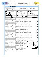
Page 34: ... START UP MAX XX X UPWARD start adjustment 99 99 A Ý Þ 4 6 SLOW UP MAX XX X UPWARD levelling speed adjustment 99 99 B Ý Þ 4 7 HIGH DN MAX XX X DOWNWARD high speed adjustment 99 99 C Ý Þ 4 8 SLOW DN MAX XX X DOWNWARD levelling speed adjustment 99 99 B Ý Þ 4 9 OFFSET V0 UP XXX mm Ý Þ UPWARD levelling space adjustment in NOMINAL speed 0 600 mm 4 10 OFFSET V0 DN XXX mm Ý Þ DOWNWARD levelling space adj...

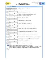
Page 35: ... 5 7 P MIN XX X bar Minimum pressure 1 0 10 0 bar medium value 5 bar Ý Þ 5 8 P FULL LOAD XX X bar Full load pressure 80 of nominal load 12 0 45 0 bar Ý Þ 5 9 P OVERLOAD XX X bar Overload pressure 110 of nominal load 12 0 50 0 bar Ý Þ 5 10 P MAX XX X bar Pressione di massima 140 del carico nominale 15 0 70 0 bar Ý Þ Re calculated value when the Pstat MIN value parameter 5 5 or the Pstat MAX value p...

Page 36: ...Standard Slow Extra Slow Custom Ý Þ 6 7 DEC PROFILE XXXXXXXX Deceleration profile Fast Standard Slow Extra Slow Custom Ý Þ 6 8 START DELAY X X s Delay start closing VB Time to start the motor pump 0 2 5 0 s 7 DOWNWARD PARAMETERS NGV VER XX XXX 7 DN PARAMETERS Ý Þ 7 1 NOM SPEED V0 X XX m s Enter required nominal downward speed m s es 0 63 Ý Þ 7 2 INT SPEED V1 X XX m s Indicates the Intermediate spe...

Page 37: ...t please refer to the Overpressure Valve VS Adjustment chapter This routine needs VS and V0 input signals for working Press ENT to start the routine The display blinks while the routine is working at the end of the routine the fixed value is the adjustment value of the overpressure valve Press ESC to exit and ENT to start again Ý Þ 9 2 PIPE RUPTURE ENT Start Start the routine for the test of the p...

Page 38: ...NO TEST condition necessary for the normal working of the sysstem To return to normal operating condition parameter you should select NO TEST and press ENT to confirm the codition change before to exit pushing ESC Ý Þ 9 8 S3 TUNING ENT Start Start the routine that allows to place the sensor S3 in the correct position The routine open the VB allowing to move the sensor in the exact lighting positio...

Page 39: ...re 5 C 12 OIL TEMP HI Maximum oil temperature 5 11 COOL TEMP 13 S3 CLOSED Contact S3 VBO closed with lift stopped 14 S3 OPENED Contact S2 VBC opened with lift stopped 15 S1 NOT OPEND Contact S1 VRP did not opened during starting downward travel 16 S1 NOT CLOSD Contact S1 VRP did not closed during end of downward travel 17 S2 NOT CLOSD Contact S2 VBC did not closed during end of downward travel 18 ...

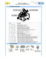
Page 40: ...e gaskets seal þ 6 Oil level check up þ 6 Characteristics of the oil þ 6 Motor protection operation þ 6 Filters þ 1 Pressure check þ 6 Pressure gauge shut off 4 þ 6 Pressure test static pressure x2 þ 6 Ball valve seal 6 Labels signs and schemes þ 6 Overall check up 5 6 3 MAINTENANCE SCHEDULES What to do see image Valve gaskets seals At the end of installation and during check ups verify the gasket...

Page 41: ...the pressure gauge valve 4 Open the ball valve B Open the hand pump valve N for about 1 minute Close the hand pump valve N Close the ball valve B Operate the hand pump M until the required pressure is reached checking it on hand pump pressure gauge O At the end of the test discharge the pressure to zero by pressing the push button on VMD see image up Close the pressure gauge shut off 4 Disconnect ...

Page 42: ... the parameter 5 11 COOL TEMP is 70 C set the value up to 70 C If the parameter 5 11 COOL TEMP is 70 C probably you must install an heat exchanger 13 S3 CLOSED Contact S3 VBO closed with lift stopped 14 S2 OPENED Contact S2 VBC opened with lift stopped 15 S1 NOT OPEND Contact S1 VRP did not opened during starting downward travel 16 S1 NOT CLOSD Contact S1 VRP did not closed during end of downward ...

Page 43: ...sed 5 The system starts in up direction with an not regular acceleration it starts with a little burst and immediately return to the correct acceleration The starting time is not correct the oil output line was open in advance and the oil reach the piston until the motor is at full Increase the value of the menu point 6 8 to delay the oil output line opening 6 The system run irregularly and inaccu...

Page 44: ...Menu 4 2 4 4 min car empty 4 6 e 4 8 max car with full load 10 The system stops during the switching from nominal speed to slow speed with the car empty or full loaded If the basic settings are correct Menu 5 the slow speed 6 4 and 7 4 or the low speed offsets 4 2 4 4 4 6 e 4 8 should be too low Input the recommended values for the menu points 6 4 e 7 4 or increase the offsets of the slow speed 4 ...

Page 45: ...sensors should be done with the system stopped S1 VRP S2 VB Close S3 VB Open 6 5 1 SENSOR S1 ò 1 2 3 1 4 6 5 2 SENSOR S2 õ 1 2 3 1 4 6 5 3 SENSOR S3 8 Using the programmer PT01 select the function 9 8 S3 tuning and activate it pressing ENT 9 Proceed as show in the image 10 deacrivate the function 9 8 S3 tuning by pressing ESC ö 1 2 3 P 1 4 ...

Page 46: ...1 0991 483 EN 21 12 2011 ENG 1 05 46 46 NGV A3 VALVE MANUAL INSTALLATION USE AND MAINTENANCE 7 CERTIFICATES ...

Page 47: ... ...

Page 48: ...I PER ASCENSORI GMV SPA VIA DON GNOCCHI 10 20016 PERO MILANO ITALY TEL 39 02 33930 1 FAX 39 02 3390379 HTTP WWW GMV IT E MAIL INFO GMV IT Azienda CERTIFICATA UNI EN ISO 9001 Doc n 1 0991 483 Rev 1 05 21 12 2011 File NGVA3 MI 02 10991483EN doc J2 ...

Reviews: