13
Assembling the system
Required Tools
• H
ex wrenches 4, 5, 6, 8
• S
ocket wrench 15
• S
crewdriver set
• Ph
illips head screwdriver set
Assembling the stand
Please preview all steps and parts described below here before you start assembling. It will help you
to anticipate on every step to come.
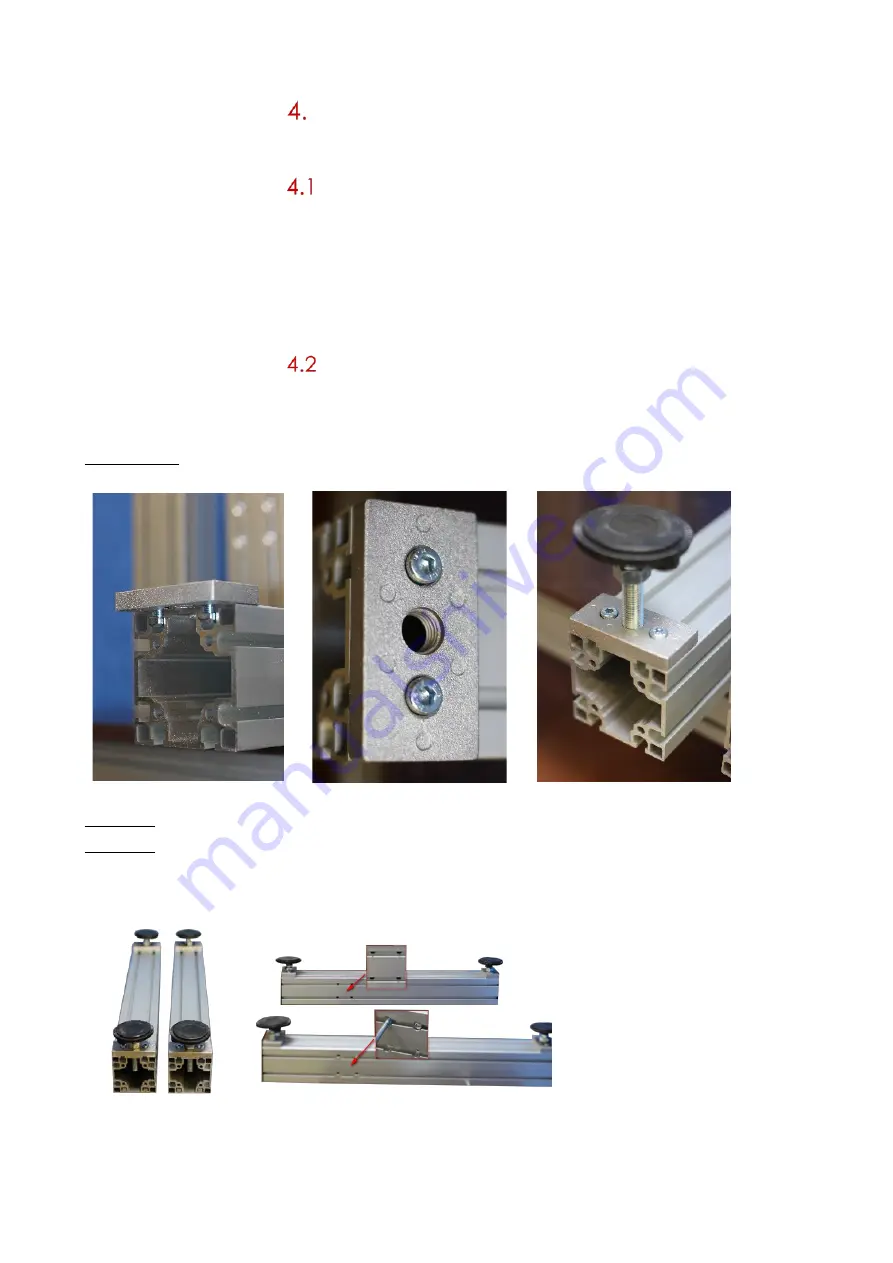
Picture 1 – 3: mount the four round feet to the corners of the 2 longer alloy profiles (check also pic.
4 + 5!):
Pic. 1
Pic. 2
Pic. 3
Picture 4: mount the feet on the faces which do not have screw holes
Picture 5: let the narrow ends of the screw holes face each other on the inside whilst mounting the
feet.
Pic. 4
Pic. 5
Summary of Contents for AG3000
Page 28: ...28 Pic 7 select the icon shown below to return to main menu Pic 8 Back on main menu ...
Page 36: ...36 Pictures 2 Picture 3 ...
Page 43: ...43 10 Wire diagrams 10 1 Power and signals schematic 10 2 Control unit picture ...
Page 44: ...44 10 3 Power circuits 10 4 Connector rack detailed view ...
Page 45: ...41 10 5 Connector rack diagram ...
Page 46: ...42 10 6 Electro pneumatic diagram 10 6 PLC Printer applicator port diagram ...


