18
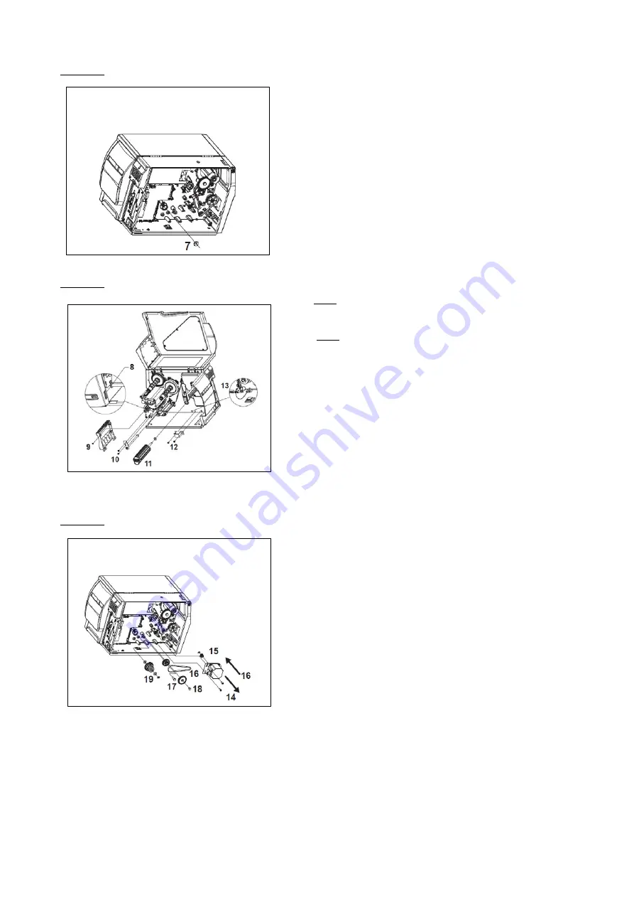
Picture 4:
Step 7. Insert the second bearing from the left sight
Picture 5:
Step 8. SKIP this step! Not relevant for applicator use
.
Step 9. SKIP this step! Not relevant for applicator use.
Step 10. Install the diverter pulley
Step 11. Insert the rewinder shaft into the bearings
Step 12. Install the “rewinder full” sensor
Step 13. Plug in the sensor connector
Picture 6:
Step 14. Remove the motor.
Step 15. Install the 22T cogwheel and its retaining ring.
Step16. Install the motor and the rewinder drive belt
Step 17. Install this gear set
Step 18. Install this gear set
Step 19. Install the clutch
i
:
The default torque setting of the clutch suits the AG3000 requirements. Please check the
printer service manual in case the torque needs to be adjusted at some point.
i
:
GO TO § 4.4 (APPLICATOR INTERFACE INSTALLATION) BEFORE RE-INSTALLING THE PRINTER
COVER!
Summary of Contents for AG3000
Page 28: ...28 Pic 7 select the icon shown below to return to main menu Pic 8 Back on main menu ...
Page 36: ...36 Pictures 2 Picture 3 ...
Page 43: ...43 10 Wire diagrams 10 1 Power and signals schematic 10 2 Control unit picture ...
Page 44: ...44 10 3 Power circuits 10 4 Connector rack detailed view ...
Page 45: ...41 10 5 Connector rack diagram ...
Page 46: ...42 10 6 Electro pneumatic diagram 10 6 PLC Printer applicator port diagram ...


