background image


10

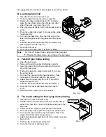
9.  Push feed button (part 7) to feed out label. 
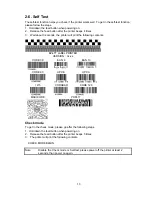
10. Lay the printer downs with the front cover up, on the table 

and start it to print. 

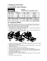
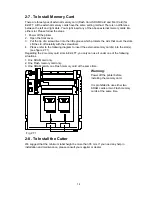
2-4. To Connect the Printer to an Interface 

1.  Be sure the power switch of the printer is off. 
2.  Plug the power adapter into the printer power jack. 
3.  Connect the printer to an interface (parallel or serial port). 
4.  Turn on the power switch, and the power LED is light red or green. 

(Refer Chapter 2, Section 2 and 3, to load the ribbon and label roll.) 

Meaning of Beep Sound 

1.   Beep 1 time: Power on and printer is ready 
2.   Beep 2 times: Check the label roll. Maybe the roll is not yet loaded or not in the correct 

position, or there are no labels. 

3.   Beep 3 times: Check ribbon. Maybe the ribbon is not yet loaded or finished out, or the 

setup is not correct. 

4.   Beep 4 times: Printer head assembly is unlocked. 

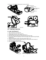
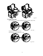
2-5. Using the Stripper 

Stripper (Peeler) helps you separate the printed label from the liner paper one at a time. Only 
when the separated label has been taken away, will another label be printed automatically. 
1.  Open the front cover and back cover. 
2.  Press the printer locks (part 14) to loosen the printer head assembly, and turn over the 

head assembly. 

3.  Check if the stripper arm is on “on” position. If not, press it down to “on” position.   
4.  Load the label roll with at least 4 inches of liner paper past the platen (see figure 2.5.1a). 
5.  Put back the printer head assembly and fasten it. 
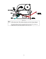
6.  Insert the front edge of the 4-inch liner paper between the stripper bar (part 19) and the 

stripper roller (part 20).   

7.  Power on the printer, and press the paper feed button a few times until the front edge of the 

liner paper appears through the stripper roller (make sure again: the stripper arm is now 
turned down -- strip on). 

8.  If the liner paper does not appear at the right angle under the stripper roller, you should 

adjust the label roll to right position (Loosen the printer head assembly again and lift up the 
stripper arm, then you can adjust the label). Make sure the edge of the first label is under 
the gap sensor (see figure 2.5.1b). 

9.  Turn up the strip sensor (see figure 2.5.2a), and you are ready to start printing the labels 

(see figure 2.5.3). (Figure 2.5.2b show you how to turn down the strip sensor.) 

Summary of Contents for EZ-2P

Page 1: ...EZ 4TT 4TK 2P 4P User s Manual ...

Page 2: ...s may cause harmful interference to radio communications Operation of this equipment in a residential area is likely to cause harmful interference in which case the user will be required to correct the interference at his own expense EMS AND EMI COMPLIANCE STATEMENT FOR EUROPEAN USERS This equipment has been tested and passed with the requirements relating to electromagnetic compatibility based on...

Page 3: ...ation die das Gerät vor Überheitzung schützen Sorgen sie dafür daß diese Öffnungen nicht adgedeckt werden 4 Durch die Belüftungsöffnungen dürfen niemals Gegenstände oder Flüssigkeiten in das Gerät Gelangen 5 Dieses Gerät kann bis zu einer Umgebungstemperatur von maximal 25 C betrieben werden 6 Die Ausgangswerte dürfen nicht die auf dem Typenschild angegebenen Werte überschreiten 7 Die Steckdose mu...

Page 4: ...NG UP 7 2 2 LOADING THE RIBBON 7 2 3 LOADING LABEL ROLL 8 2 4 TO CONNECT THE PRINTER TO AN INTERFACE 10 2 5 USING THE STRIPPER 10 2 6 SELF TEST 13 2 7 TO INSTALL MEMORY CARD 14 2 8 TO INSTALL THE CUTTER 14 3 MAINTENANCE AND ADJUSTMENTS 15 3 1 CLEANING THE PRINTER HEAD 15 3 2 ADJUSTING GAP SENSOR SENSITIVE 15 3 3 ADJUSTING THE START PRINT POSITION 16 3 4 ADJUSTING THE PRINTER HEAD PRESSURE SCREWS 1...

Page 5: ... external label roll Print method Thermal transfer printing and Direct thermal printing Print Width 4 09 104 mm 4 268 108 42mm Print speed 3 per second Peel off function Standard min label height 18mm Option Cutter option Optional user friendly installation no training needed Standard RAM 256K SRAM 8 203 mm print length 512K SRAM 8 203 mm print length Flash card M1 1MB M2 2MB for download label fo...

Page 6: ... and PDF 417 Paper sensor types 1 Plain paper detector 2 Label gap size detector 3 Black line reflect sensor detector 4 Stripper sensor detector Working Environment Operating Temperature 40 F to 104 F 5 C to 40 C Storage Temperature 40 F to 140 F 40 C to 60 C Humidity 10 to 90 non condensing free air Power requirement AC 13 5V 16 0V 4A 5A DC 18 0V 24 0V 4A 5A 1 3 Contents Fig 1 3 1 1 4 EZ 4TT Prin...

Page 7: ...P Switch 11 Power Switch 25 Fan Fold Media Entry 12 Ribbon Rewind Spindle 26 Label Guide Adjustable Horizontally 13 Printer Head Pressure Adjusting Screws 27 Gap Sensor Assembly 14 Printer Lock 2 EA left right 28 Printer Head Assembly Fig 1 4 1 Fig 1 4 2 27 28 26 Fig 1 4 3 ...

Page 8: ...nons on the left and right sides part 5 Lay down the back cover see figure 2 2 1 step 2 3 Open the front cover by pressing the two locking tenons on the left and right sides part 4 Lay down the front cover see figure 2 2 1 step 3 Fig 2 2 1 4 By pressing toward the cap side take out the ribbon supply spindle part 21 and the rewind spindle part 12 see figure 2 2 2 5 Install a new ribbon onto the sup...

Page 9: ... 17 3 Put back label roll into the core guide see figure 2 3 1 4 Press the printer locks part 14 to loosen the printer head assembly 5 Turn over the printer head assembly Pass the front edge of the label roll through beneath the gap sensor 6 Adjust the label guide to close to the roll s edge see figure 2 3 2 7 Put back the printer head assembly and fasten it by pressing down from the top of it 8 C...

Page 10: ...ll Stands part 23 3 Insert the paper into the Fan fold Media Entry part 25 of the back cover 4 Push and release the printer locks part 14 to open the printer head 5 Turn over the opened printer head assembly Pass front edge of the labels under the gap sensor 6 Adjust the label guide part 26 to fit in the label s edge see figure 2 3 2 7 Put back the printer head assembly and fasten it 8 Close the f...

Page 11: ...abel be printed automatically 1 Open the front cover and back cover 2 Press the printer locks part 14 to loosen the printer head assembly and turn over the head assembly 3 Check if the stripper arm is on on position If not press it down to on position 4 Load the label roll with at least 4 inches of liner paper past the platen see figure 2 5 1a 5 Put back the printer head assembly and fasten it 6 I...

Page 12: ...5 1 To position the sensor Press the top area 3 bar area and lift from the bottom as shown in figure 2 5 2a Fig 2 5 2a Suggested way to put back the sensor Press the bottom area right below the 3 bar Fig 2 5 2b ...

Page 13: ... 3 Note Lift the strip arm to off position whenever you do not choose stripper Although the stripper function can support a label as short as 18 mm high we suggest that the minimum label height be more than 20 mm ...

Page 14: ... the following contents EZ 4TT LABEL PRINTER VERSION Vx xx CODE 39 EAN 8 EAN 13 CODE 93 UPC E UPC A I 2 5 CODABAR CODE 128 MAXI CODE PDF417 Check mode To get in the check mode please go after the following steps 1 Hold down the feed button when powering on 2 Release the feed button after the printer beeps 5 times 3 The printer will print the following contents CHECK MODE BEGIN Note Disable the Che...

Page 15: ... off carefully with the screwdriver 4 Please refer to the following diagram to insert the external memory card s into the slot s see figure 2 7 1 Regarding the 2 memory card slots in EZ 4TT you only can use it under one of the following situations 1 One SRAM card only 2 One Flash memory card only 3 One SRAM card one Flash memory card at the same time Fig 2 7 1 Warning Power off the printer before ...

Page 16: ...h higher sensitivity less sensitivity VR Fig 3 2 1 a When using the label roll 6 Remove the label from the liner Load the liner paper under the sensor 7 Press the micro switch and gently adjust the Variable Resistor Right after the adjustment press the paper feed button at least 7 times do not loosen the micro switch until the LED light turns red 8 Put the label roll with labels on the liner under...

Page 17: ...4 Insert the label roll and move the label guide to close to the roll s edge 5 Put back and fasten the printer head assembly then you can try printing a label to test the gap sensor position X start print position paper feed direction Fig 3 3 1 0 Gap Sensor Label Guide 4mm Left margin line Fig 3 3 2 3 4 Adjusting the Printer Head Pressure Screws increase pressure decrease pressure When opening the...

Page 18: ...nkled Adjust the printer head pressure screws part 13 to increase the pressure Check if using correct power source Difficult to load label roll Labels stuck in the printer When printing out some dots missing Clean printer head with alcohol If the label glue is stuck to printer head apply alcohol to printer head and wipe with soft cloth softly Replace printer head Printing position not correct Chec...

Reviews: