background image

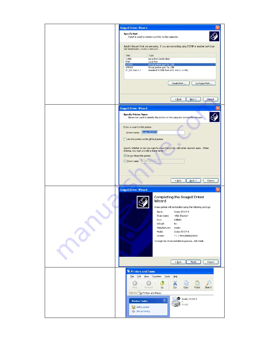
6. 

Select connection port. 

7. 

Enter the printer name and 
set printer sharing option.     

8. 

A description page of printer 
settings will be displayed after 
all settings are completed.   

 
9. 

Check if all printer settings 
are correct and then press 
Finish to start copying driver 
files. 

 
10.  Wait for file copying finished 

and complete the installation.   

11.  After the driver installation is 

complete, there should be a 
new printer model on 
Windows "Printer and Faxes" 
setting.         


EZ-DT-2/EZ-DT-4 User’s Manual 
 

14

Summary of Contents for EZ-DT-2

Page 1: ...User s Manual EZ DT 2 EZ DT 4 P N 920 012511 03 Rev A 08 2009 ...

Page 2: ...eit in das Gerät gelangen so ziehen sofort den Netzstecker Anderenfalls besteht die Gefahr eines lebensgefährlichen elektrischen Schlags 5 Wartungs und Reparaturarbeiten dürfen aus Sicherheitsgründen nur von autorisierten Personen durchgeführt werden 6 Bei Wartungs und Reparaturarbeiten müssen die Sicherheitsvorschriften der zuständigen Berufsverbände und Behörden unbedingt eingehalten werden 7 Be...

Page 3: ...5 ONLY qualified service personnel for safety reason should open equipment 6 Don t repair or adjust energized equipment alone under any circumstances Someone capable of providing first aid must always be present for your safety 7 Always obtain first aid or medical attention immediately after an injury Never neglect an injury no matter how slight it seems CAUTION Danger of explosion if battery is i...

Page 4: ...dule Installation 18 3 3 EZ DT 2 Ethernet Module Installation 20 3 4 EZ DT 4 Ethernet Module Installation 23 4 PRINTER SETTING 25 4 1 FEED Key 25 4 2 LED Status 25 4 3 Auto Sensing 25 4 4 Self Test 26 4 5 Error Messages 27 5 MAINTENANCE AND ADJUSTMENT 28 5 1 Print Head Module Installation Removal Instruction 28 5 2 Thermal Print Head Cleaning 30 5 3 Adjust the Cutter 30 5 4 Black Mark Paper 31 5 5...

Page 5: ...us form gap labels black mark sensing and punched hole label length set by auto sensing or programming Media Width 0 6 15 mm Min 2 36 60 mm Max Thickness 0 003 0 06 mm Min 0 008 0 20 mm Max Label roll diameter Max 5 127 mm Core diameter 1 1 5 25 4 mm 38 1 mm Width 1 25 4 mm Min 4 64 118 mm Max Thickness 0 003 0 06 mm Min 0 008 0 20 mm Max Label roll diameter Max 5 127 mm Core diameter 1 1 5 25 4 m...

Page 6: ...ower Green Orange and Red Control key FEED Real Time Clock Standard Power Auto Switching 100 240VAC 50 60Hz Environment Operation temperature 41 F to 104 F 5 C to 40 C Storage temperature 4 F to 122 F 20 C to 50 C Humidity Operation 30 85 non condensing Storage 10 90 non condensing Agency Approvals CE EMC FCC Class A CB CCC Dimension Length 8 58 218 mm Height 6 77 172 mm Width 3 94 100 mm Length 8...

Page 7: ...N C GND 5 5 GND DSR 6 6 RTS RTS 7 7 CTS CTS 8 8 RTS RI 9 9 N C PC PRINTER Note The total current output from serial port can not exceed 500mA USB Interface Connector Type Type B PIN NO 1 2 3 4 FUNCTION VBUS D D GND Internal Interface UART1 wafer Ethernet module N C 1 1 N C TXD 2 2 RXD RXD 3 3 TXD CTS 4 4 RTS GND 5 5 GND RTS 6 6 CTS E_MD 7 7 E_MD RTS 8 8 CTS E_RST 9 9 E_RST 5V 10 10 5V GND 11 11 GN...

Page 8: ...5 3 1 LED Light 2 FEED Key 3 Top Cover 4 Power Switch 5 Cover Open Button 1 2 3 6 5 4 1 Print Head Lift 2 Label Roll Holder 3 Print Mechanism 4 Label Roll Core 5 Label Guide 6 Front Cover Piece EZ DT 2 EZ DT 4 User s Manual 7 ...

Page 9: ...3 2 1 1 Platen Cover 2 Label Sensor 3 Platen Roller 1 3 2 4 1 Power Socket 2 USB Port 3 Fan Fold Label Insert 4 Serial Port RS 232 1 2 1 Bottom Case Cover 2 Hang Holes EZ DT 2 EZ DT 4 User s Manual 8 ...

Page 10: ...and release the lock of Label Roll Core 3 Pull up the Label Roll Holder and lift the Label Roll Core upward 4 Place a new label roll onto the Label Roll Core 5 Flip the Label Roll Core downward and pull back the Label Roll Holder 6 Pull and lock the Label Roll Core to the original position EZ DT 2 EZ DT 4 User s Manual 9 ...

Page 11: ...he label under the Label Guide and stretch it frontward 8 Pull the Label Guide inward and make it fit the edge of label 9 Close the Top Cover to complete the label installation EZ DT 2 EZ DT 4 User s Manual 10 ...

Page 12: ...shows 3 Whirl the Label Roll Core back to the original position 1 Core A When the lock hole of Label Roll Core is on upper side it applies to 1 core B When the lock hole of Label Roll Core is on lower side it applies to 1 5 core Note You can also distinguish it by the index on the Label Roll Core as shown in figure 1 5 Core EZ DT 2 EZ DT 4 User s Manual 11 ...

Page 13: ...er cable plug the cable switch to the power socket and then connect the other end of the cable to the printer power socket 3 Connect the cable to the USB Serial port on the printer and on the PC 4 Power on the printer and the LED light will shine EZ DT 2 EZ DT 4 User s Manual 12 ...

Page 14: ...rives folder 2 Select the icon of driver file and click it to start the installation 3 Follow the instruction on screen to keep the installation going Then the Driver Wizard utility should run automatically 4 Select Install printer drivers 5 Select printer model EZ DT 2 EZ DT 4 User s Manual 13 ...

Page 15: ...fter all settings are completed 9 Check if all printer settings are correct and then press Finish to start copying driver files 10 Wait for file copying finished and complete the installation 11 After the driver installation is complete there should be a new printer model on Windows Printer and Faxes setting EZ DT 2 EZ DT 4 User s Manual 14 ...

Page 16: ...he max width for stripper is 110mm for DT 4 and 54mm for DT 2 2 1 1 Place the printer on a horizontal surface and open the Top Cover 2 Remove the Front Cover Piece Note You can also use coin or screwdriver to open the Front Cover Piece 3 Push the Stripper connector into printer through the cable hole as shown in figure 4 Place the Stripper on the fillister Align the Stripper with 2 notches on the ...

Page 17: ...om case cover 6 Tighten the screws to fix the Stripper in location 7 Plug the connector into the main board Note There are 2 sockets on the main board one is for stripper installation another is for cutter installation Before plugging the connector into socket please check the pin first 8 Lock the Bottom Case Cover For EZ DT 2 please tighten the screw of Bottom Case Cover 9 Turn the printer back t...

Page 18: ...d for stripper is suggested to be at least 20mm in height Suggestion When printing with stripper module it is suggested to set the stop position E to 9 for DT 4 and 8 for DT 2 13 Follow the direction as shown in figure to feed the liner across the stripper 14 Flip the stripper upward to close it 15 Press the FEED key to adjust the position of label and complete the installation EZ DT 2 EZ DT 4 Use...

Page 19: ... 000 cuts for paper weights up to 120g and 500 000 cuts for paper weights 120g to 170g Note3 The max paper cutting width is 114mm Note4 The label paper that used for cutting is suggested to be at least 30mm for DT 4 and 40mm for DT 2 in height 1 Place the printer on a horizontal surface and open the Top Cover 2 Remove the Front Cover Piece 3 Push the Cutter connector into printer through the cable...

Page 20: ...check the pin first 8 Lock the Bottom Case Cover For EZ DT 2 please tighten the screw of Bottom Case Cover 9 Turn the printer back to proceed to the label installation 10 o It is n se label inside paper when printing with cutter module Follow the instruction on Chapter 2 1 to install the label N te ot suggested to u 11 Feed the label through the Cutter and press the FEED key to complete the instal...

Page 21: ...off and the power cable is unplugged Place the printer onto a smooth surface and flip the whole printer side down the bottom case screws as ated in figure unit up 2 Unscrew indic 3 Remove the Front Cover Plate 4 ment and the top Lift the middle compart cover up 5 Unplug the power connector on the mainboard 6 Remove the middle compartment and the top cover together with the mainboard 7 ompartment a...

Page 22: ...nto the socket on mainboard Then the figure showed to keep the connector in place place the other end of Module Connection Wire connector among the electric capacities as 14 Align the Ethernet module to the Eth port and plac ernet e the module upon the mainboard Note Please arrange the Module Connection Wire to keep it away from the hole which is marked with circle in figure 15 Tighten the Etherne...

Page 23: ...ttin to en corre Note e organize all cables and wires well before g middle compartment and top cover back sure that the printer can be assembled ctly 20 Assemble the Front Cover Plate 21 Tighten the bottom case screws 22 The Ethernet Module installation is complete Note After the Ethernet module installation is completed please send the XSET USBETHERNET 1 printer command to printer for activating ...

Page 24: ...ce the printer onto a smooth surface and flip the whole printer unit upside down 2 Unscrew bottom case screws as indicated in figure Make sure the 3 ver Open Button and open the top cover Press the Co 1 1 2 2 4 Remove the Front Cover Plate 5 Lift the middle compartment and the top cover up 6 Loosen hexagonal screws on both sides of Push the mainboard slightly to the direction ndicated in figure th...

Page 25: ...ard and the other end to the Ethernet module 15 Put the middle compartment back and assemble it with bottom compartment of the printer 16 Install the Front Cover Plate 17 Tighten bottom case screws to complete No p XS THERNET 1 printer command to rinter for activating the Ethernet connection function Please mind that USB port will be deactivated once the Ethernet connection function is activated t...

Page 26: ...l status Press and hold the FEED Key then power on the printer Red Flash 3 Auto Sensing Mode Printers are currently in Auto Sensing Mode The calibration will be performed and a Self Test page will be printed out to show the configurations of printer For more detail about Auto Sensing Mode please refer to next section For the descriptions of Self Test page please refer to page 26 4 3 Auto Sensing P...

Page 27: ...TTF S IN MEMORY 2048K BYTES FREE MEMORY S4 H10 R000 R200 W10 Q48 3 Option D0 O0 See through Sensor AD 411 841 985 22 P sor switch or Dump Mode please 000 FORM S IN MEMORY 000 GRAPHIC S IN MEMORY 000 FONT S IN MEMORY 000 ASIAN FONT S IN MEMORY 000 DATABASE S IN MEMORY AD Code age 850 Test pattern Number of DRAM installed Speed Density Ref Point Print direction Label w gth Cutter Sensor Setting Code...

Page 28: ...rmal paper feed rd tags or behind the label k mark adjust l usage 2 beeps twice Possible causes ca paper fall into the gap d platen roller can t fin c gap black mark bla paper out Please according to actua Red mory is full printer w out Memory full e unnecessary data in the 2 beeps twice Me ill print Delet memory Red 2 beeps twice Can t find the file printe out Filename can not be found out les th...

Page 29: ...Top Cover Note Po ff th before remo installing the print head val Instruction to se Print hich is Hea wer o e printer ving or 2 Flip the Print Head Lift downward to release it 3 The Print Head cke flipped downward after Print Head Lift is released Bra t can be 4 Remove the Print Head Connector EZ DT 2 EZ DT 4 User s Manual 28 ...

Page 30: ...r new print head is installed tighten the Print Head Screws plug the re ft to complete the installation hold the front end of print head to remove it and install new print head Print Head Connector resto the Print Head Bracket and lock the Print Head Li EZ DT 2 EZ DT 4 User s Manual 29 ...

Page 31: ... cleaning the print head with soft any metal or hard it ar printouts ma use alcohol to te1 ly cleaning for the pri mended te2 W cloth make sure there is no particles attached on 5 3 Adjust the Cutter When jam may happen somet d by adjusting the cutter 1 T d to see the C crew Loose the Cutter Cover Screw to remove the Cutter Cover using Cutter paper imes It can be solve urn the printer aroun utter ...

Page 32: ...reverse side of label cannot b ircumstance please make sure the black Z DT 2 I r is 60mm the size and location of black mark should be length of A is more than 13 1mm f the width of black mark pape z z length of B is less than 5mm z length of C is more than 8 1mm EZ DT 4 If the width of black mark paper is 118mm length of A is more than 10 05mm length of B is less than 1 95mm the size and location...

Page 33: ...as error When printing part of the label wasn t Check if Thermal Print Head is stained or dusted Use internal command T to check Thermal Print Head can print completely Check the media quality printed completely The printout is not in desired position Check if sensor is covered by paper or dust Check if liner is suitable for use please contact reseller for more information Check if label roll edge...

Page 34: ...Appendix 1 EZ DT 2 Certifications EZ DT 2 EZ DT 4 User s Manual 33 ...

Page 35: ...EZ DT 2 EZ DT 4 User s Manual 34 ...

Page 36: ...EZ DT 2 EZ DT 4 User s Manual 35 ...

Page 37: ...EZ DT 2 EZ DT 4 User s Manual 36 ...

Page 38: ...EZ DT 2 EZ DT 4 User s Manual 37 ...

Page 39: ...2 EZ DT 4 Certifications EZ DT 2 EZ DT 4 User s Manual 38 ...

Page 40: ...EZ DT 2 EZ DT 4 User s Manual 39 ...

Page 41: ...EZ DT 2 EZ DT 4 User s Manual 40 ...

Page 42: ...EZ DT 2 EZ DT 4 User s Manual 41 ...

Page 43: ...EZ DT 2 EZ DT 4 User s Manual 42 ...

Page 44: ...EZ DT 2 EZ DT 4 User s Manual 43 ...

Reviews: