27
3
-
7
-
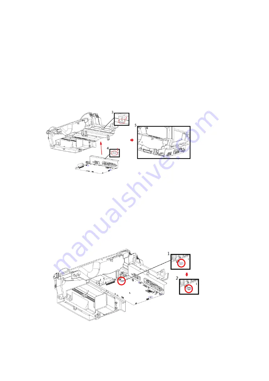
2 Assemble Mainboard Module
(Note: Please take a closer look at chapter 5 to see further information of the precise map of the mainboard
connectors.)
Step
1. Assemble Mainboard Module
Please place the mainboard on the marked areain the diagram and match the tenon(red circle 1) to
the base mortise(red circle 2) carefully.
Step
2. Tighten Screws
Tighten Screws (red circle marked)
Summary of Contents for RT700 SERIES
Page 8: ...5 2 Spare Parts List 2 1 Main Mechanism RT 700i RT 700i ...
Page 39: ...36 3 11 Switching Power Adapter 021 70i005 000 ...
Page 40: ...37 3 12 Print Frame Hook 021 R70005 000 ...
Page 41: ...38 3 13 Main Frame Hook 021 R70008 000 ...
Page 42: ...39 3 14 Label Holder 021 R70009 000 ...
Page 43: ...40 3 15 One Way Clutch Holder Module 021 R70010 000 ...
Page 44: ...41 3 16 Peeler Module 031 R70001 000 ...
Page 45: ...42 3 17 4 Cutter Module RGG120 VE Whole Cut 031 R70002 001 ...
Page 46: ...43 3 18 Wireless Bluetooth Module Metal Cover 031 70i001 001 ...
Page 49: ...46 4 2 Definition of Pin ...


