3 Technical Description
G PCIe 6281
13
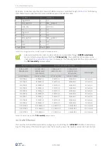
3.4.4 LEDs/ Status Indication
The LEDs arranged on the front panel provide information about the current operating status of the
G PCIe 6281
Multibus Controller. The display states of the LEDs are explained in the following table:
LED1
LED2
LED3
LED4
Comment
constantly ON
Controller is not running (Error)
blinking alternately
Bootloader software is running
blinking
Firmware is running
ON (shortly)
Execution of a firmware command for onboard
interfaces
ON
Ethernet connection established
Table 3.7 Display states of the status LEDs
3.4.5 Power Supply
The
PCIe
board of the
G PCIe 6281
Multibus Controllers is supplied via the PCIe interface.
3.4.6 Galvanic Isolation
Overvoltages can damage expensive test equipment or lead to unsafe test results. The potential separation pro-
tects against overvoltages and can suppress dangerous surges. It also prevents ground loops responsible for da-
ta errors due to ground potential differences.
On the
G PCIe 6281
Multibus Controller, the host system is electrically isolated from the interfaces leading to the
RJ.5 connectors. This includes the CAN/ CAN FD, LIN/ K-Line, Automotive Ethernet and FlexRay communication
interfaces as well as the digital inputs and outputs.
3.4.7 SYNC
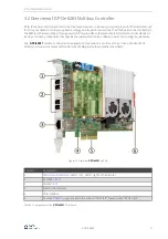
There are two SYNC (Synchronization) connectors on the back of the PCIe board of the
G PCIe 6281
Multibus
Controller. These can be used to connect multiple PCIe boards so that the cards can synchronize with each oth-
er. "SYNC left" (see
Overview of G PCIe 6281 Multibus Controller
) will be connected with the left placed card and
"SYNC right" with the right placed card. This means that the "SYNC left" connector of one PCIe board is connect-
ed to "SYNC right" of the other board.
The SYNC connectors are not to be used for any purpose other than the above purpose. The pin as-
signment will therefore only be issued on request.


