background image

17 

RELAY CONTROL SYSTEM ELECTRICAL INSTRUCTIONS 


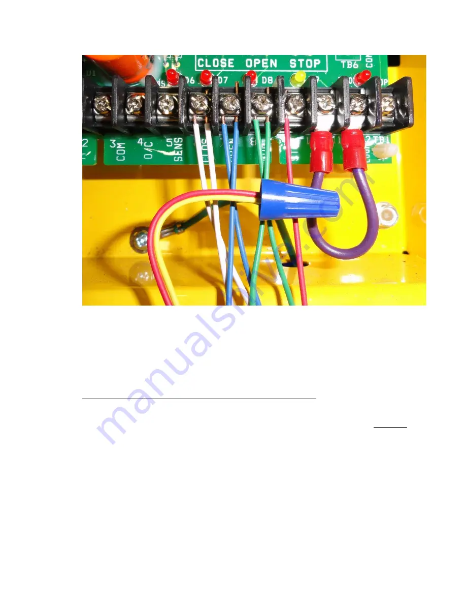
The wiring for the additional control station is now complete.  You can continue to add control 
stations by following this same procedure. Connect the blue, white, and green wires to the 
corresponding terminals in the operator.  Disconnect the red wire from the previous station 
from the #9 Terminal, connect it to the yellow wire for the new station (wire nut), and connect 
the red wire for the new station to Terminal #9. 

ADDING PULL CORD OR SINGLE BUTTON CONTROL STATIONS:


The External Operator supports N/O (Normally Open) Pullcord Switches, N/O Single Button 
Control Stations, and any other N/O dry contact.  All N/O switches should be wired in PARALLEL 
and the wiring junctions can be made either at the switches (daisy-chain) or at the External 
Operator (Homerun).  Switches should be connected using two-conductor wiring (supplied) and 
terminated at the External Operator at the #3 (COM)  and #4 (O/C) terminals.  Color codes are 
not important. 


Summary of Contents for 2000

Page 1: ...VAC 60Hz power wiring and the low voltage control wiring While the low voltage side of the control system can be configured and properly wired by anyone who has a rudimentary understanding of electrical circuitry the power wiring should be performed by an electrical professional and done in such a manner to conform to all local and national wiring codes and regulations READ THIS MANUAL CAREFULLY O...

Page 2: ...ure that the branch circuit and conductor size can support this load requirement Low voltage can cause erratic behavior and operator overheating Locate the rotary selector switch on the printed circuit board and ensure that it is set to C2 position 0 as shown in the following photo Power and ground are connected to the operator as shown in the following photo Photo 19 ...

Page 3: ...OTOR CONNECTIONS The following schematic shows your Motor and Limit Control wire connection points within the control panel These two cables then run up to your motor and connect to your Motor Winding wires and Limit Switches respectively See diagram on next page ...

Page 4: ... Locate the 6 conductor wire marked control and remove the insulative material preparing each conductor to make the following connections SEE NEXT PAGE FOR DIAGRAM o Blue from 6 conductor to N C side right of open limit switch o Black from 6 conductor to N C side right of close limit switch o White from 6 conductor to COM side left of open limit switch o Green from 6 conductor to COM side left of ...

Page 5: ...l stations with N O Open and Close buttons The Stop buttons must be N C The low voltage control connections for the primary first station should be made with the 4 conductor Thermo Wire that was included with your kit Although the color codes are arbitrary Goff s has selected the following standard CONTROL BUNDLE 6 CONDUCTOR ...

Page 6: ...ould be made with the 4 conductor Thermo Wire that was included with your kit Although the color codes are arbitrary Goff s has selected the following standard Green 8 COM Red 9 STOP Blue 7 OPEN UP White 6 CLOS DOWN Single station control installations are performed by simply running the control wiring between the control station and the operator and attaching the appropriate wires to the screw te...

Page 7: ...ill not be long enough to reach the external operator in many installations We have included a junction box cover glands wire nuts and some additional 4 conductor wire so that an extension can easily be fabricated The wiring convention for the photo eye is as follows Brown 1 24Vac Power Blue 2 24Vac Power Black 5 SENS Orange 3 COM White Not Used Remove the protective rubber cap from the photo eye ...

Page 8: ...ong service life of the unit The door will open with only a momentary pressing of the Open button but it will be necessary to press and hold the Close button in order to get the door to move down This functionality will be changed when you do the final programming LIMIT INTERNAL SAFETY SWITCH Locate the 6 conductor wire marked control and remove the insulative material preparing each conductor to ...

Page 9: ...r problem It does this by limiting the amount of time that the operator will run continuously To set the time position the rotary switch on the printed circuit board to the D Run Tm position as shown in the following photo Press the Open button and allow the door to reach the fully opened position The MRT is now set Immediately proceed to the next step Convert the operator from Constant Pressure t...

Page 10: ...n be identified by a hitch pin and tag installed on the non operator end of the roll tube center shaft This pin is to remain installed during the normal operation of the door It should only be removed for maintenance service purposes and ONLY when the door is in the fully open position Removing the pin when the door is closed or partially closed may cause damage to the system and personal injury W...

Page 11: ...ose the door and verify that the Close LED is illuminated Set the rotary switch on the printed circuit board to the B Tm Cls position as shown in the following photo Press the Stop button to reset the delay time to 0 zero seconds Every press of the Open button will add 15 fifteen seconds to the delay and every press of the Close button will add 1 one second to the total time When the time delay ha...

Page 12: ... the fully closed position ADDING WIRED CONTROL STATIONS Additional hard wired control stations can be added to your external operator system There is no limit to the number of stations that can be attached to the unit The first primary control station is wired to the operator with 4 conductor wire while all subsequent stations require 5 conductor connections The Open and Close buttons on your con...

Page 13: ... 5 conductor Thermo Wire and jumper between one of the N O terminals on the Open button and one of the N O terminals on the Close button Also connect the free end of the green wire in the 5 conductor bundle to one of these terminals Connect the rest of the wires as shown in the following photo Note that the yellow and red wires go to the N C terminals on the Stop button Route the cable through one...

Page 14: ...se a short piece of green wire from the 5 conductor Thermo Wire and jumper between one of the N O terminals on the Open button and one of the N O terminals on the Close button Make another jumper between the Close button terminal and the top N O terminal on the Lock Connect the free end of the green wire in the 5 conductor bundle to the bottom N O terminal on the Lock Connect the rest of the wires...

Page 15: ...ard Green Common Red Stop Yellow Stop Return Blue Open UP White Close DOWN Remove the cover of the NEMA 1 station and cut the bonding strip between the Close and Stop button terminals See the following photo Connect the wires as shown in the following photo Note that the yellow and red wires go to the N C terminals on the Stop button ...

Page 16: ...wire connects to the same terminal as the blue wire from the primary control station Terminal 7 The white Close wire will connect to Terminal 6 and the green wire Common connects to Terminal 8 In order to connect the Stop buttons in series disconnect the red wire from the primary control station from Terminal 9 Use the included blue wire nut to fasten it to the yellow wire of the station that you ...

Page 17: ...w station wire nut and connect the red wire for the new station to Terminal 9 ADDING PULL CORD OR SINGLE BUTTON CONTROL STATIONS The External Operator supports N O Normally Open Pullcord Switches N O Single Button Control Stations and any other N O dry contact All N O switches should be wired in PARALLEL and the wiring junctions can be made either at the switches daisy chain or at the External Ope...

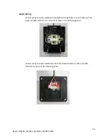
Page 18: ...rol wiring should be attached to the NEMA 4 Single Button Control Station at the lower two N O terminals s 13 14 as shown in the following photo Control wiring should be attached to the Pullcord Switch Stations at the two N O terminals as shown in the following photo ...

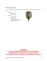
Page 19: ...res however this system only utilizes 4 Transmitter o Brown 24VDC o Blue 0VDC Receiver o Brown 24VDC o Blue 0VDC o Yellow Common o White SENS NC signal wire o Black NOT USED WARNING ALL INSTALLATION INSTRUCTIONS MUST BE FOLLOWED AND REQUIREMENTS MET FAILURE TO DO SO WILL ALTER THE PERFORMANCE AND OR CONSISTENCY OF YOUR DOOR S OPERATION ...

Reviews: