background image


2.2


    Instrument and control   

(1)


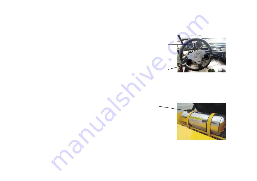
Major control switches are located on 

        the right side of the steering wheel.                                                                                                                                         

(Fig 4)   


(2)


Light switch is located on the right side of   

steering wheel. Horn button is located on   

the right side of steering wheel (Fig 4) 


(3)


Fuel tank   

Fuel tank is located above the engine and close to the   

rear carrier of the kart. Turn the lid counterclockwise   

to open and then refuel. The tank capacity is 20L. 

(Fig 5) 


Fuel tank lid 

Fig 5 

Switch panel 

Gauge 

Fig 4 

Summary of Contents for GK1100-2

Page 1: ...s and their locations 2 The use of Go Kart 6 2 1 Caution and safety note 2 2 Instrument and control 2 3 Before riding 2 4 Basic operation 2 5 Grinding in 2 6 Circuit diagram 3 Maintenance 12 3 1 Engin...

Page 2: ...In case of any problem on your Kart please refer to the trouble shooting section We hope you enjoy riding of your vehicle and we would appreciate feedback or comments from you Our company reserves al...

Page 3: ...3 1 Performance Technical Parameter and Structure of Go Kart 1 1 Performance and Specifications...

Page 4: ...4 1 2 Component location and structure Aux light Headlight Front wheel Rear wheel Back view mirror Rear shock absorber Steering wheel Front shock absorber Fig 1 Fig 2 Fig 3 Seat...

Page 5: ...ve this kart at night It s dangerous to drive on an unknown road Keep a safe distance between your kart and other vehicles Never risk drunken driving or drive the kart after taking medicine which will...

Page 6: ...located on the right side of steering wheel Horn button is located on the right side of steering wheel Fig 4 3 Fuel tank Fuel tank is located above the engine and close to the rear carrier of the kart...

Page 7: ...y return to its normal position 5 Clutch pedal Fig 6 Clutch pedal is underneath the left side of steering wheel and controlled by left foot 6 Accelerator pedal Fig 6 Accelerator pedal is located to th...

Page 8: ...seat location adjuster is in the inner side of the seat pull up to adjust when satisfied release the lever to lock Fig 9 Fig 10 11 Steering side rod Front wheel alignment can be accomplished by actua...

Page 9: ...f pedal is proper 2 No slippery Tyre 1 Proper pressure 3 No crack or cut Fuel Keep enough fuel for intended driving distance Light Check all the lamps headlights tail lamps stop lamps turn lights etc...

Page 10: ...life span of the vehicle and achieve its best performance During your driving of the first 600 miles limit the driving speed as suggested below to avoid early damage of parts due to high driving speed...

Page 11: ...11 2 6 Circuit diagram...

Page 12: ...f engine 2 A How to choose lubricating oil User should choose proper type of engine oil according to the local temperature Use SF SAE15W 40 oil in environment temperature above 20 C Use SF SAE5W 30 oi...

Page 13: ...Oil should be filled through filling port After oil filling let the engine run in idle for 3 5minutes and then check the oil level add enough if it s inadequate Fig 14 E Gear oil 85W 90 API GL 4 GL 5...

Page 14: ...he cooling liquid should be 9 F lower than the freezing point of the applied area B After 5 minute running of the engine stop it and wait for 15 minutes before you inspect the cooling water level If i...

Page 15: ...ding conditions Unusual condition requires more frequent service Time of service Items Initial service First week Monthly Quarterly Yearly Tyre pressure wear I I Brake performance I I Tightness of fas...

Page 16: ...liquid I R Note A To adjust C To clean I To inspect clean or replace if necessary L To lubricate R To replace The following are some instructions on periodical check 1 Lubricating oil check Fig 18 Ch...

Page 17: ...s 200kpa Check if there are any metal fragments or nails stuck in the tire if so remove them immediately Check if there is any crack or severe tear on the tire replace the tire if necessary 4 Battery...

Page 18: ...rking position and it is about 15 25mm Periodically inspect the thickness of the brake disc It should be replaced in case of any wear of over 1mm Periodically inspect the level of the brake fluid in t...

Page 19: ...number Item Required torque N M Kgf m 1 Front swing arm bolt 50 60 5 6 2 Rear swing arm bolt 95 105 9 5 10 5 3 Rear swing arm nut 95 105 9 5 10 5 4 Nuts at front and rear hub 65 75 6 5 7 5 5 Nuts at...

Page 20: ...spections Troubles Causes Solutions Engine suddenly stops 1 Spark short circuit 2 Carbon accumulation on spark plug 3 Ignition coil is damaged 4 Piston seized in the cylinder 1 Clean or replace 2 Remo...

Page 21: ...ge 3 Refuel 4 Clean and purge Inspection finds the spark is weak 1 Spark plug damaged 2 The clearance adjustment of the spark plug is improper 3 CDI components have defects 4 The ignition coil is dama...

Page 22: ...lectrical wire is damaged 4 Replace 5 Replace 6 Replace 7 Repair or replace The cylinder compression pressure is too low 1 Too much wear on the cylinder or piston ring 2 Piston ring gets stuck 3 Cylin...

Page 23: ...wear at the crank bearing 1 Repair the cylinder or replace it 2 Replace 3 Replace 4 Braking is bad Trouble Causes Solutions Braking is not effective 1 Excessive wear at the brake pads 2 Brake pads are...

Page 24: ...rag 5 Tyre pressure is not enough 6 Engine works improperly 7 Too much dirt in the air cleaner and cause it clogging and too thick mixed air 1 Adjust the carburetor 2 Find the repair the leakage 3 Rep...

Page 25: ...25 5 VIN Product identification number Please take down the frame number and engine number for reference The frame number is stamped on right frame at the back of the kart...

Reviews: