background image

Mighty–Mite

      A

LL

 M

ODELS

 #2035

4

MAINTENANCE INSTRUCTIONS

THE FOLLOWING SECTIONS OF THIS MANUAL ARE IN-

TENDED ONLY FOR QUALIFIED SERVICE PERSONNEL WHO

ARE FAMILIAR WITH ELECTRICAL EQUIPMENT. THESE ARE

NOT INTENDED FOR THE OPERATOR.

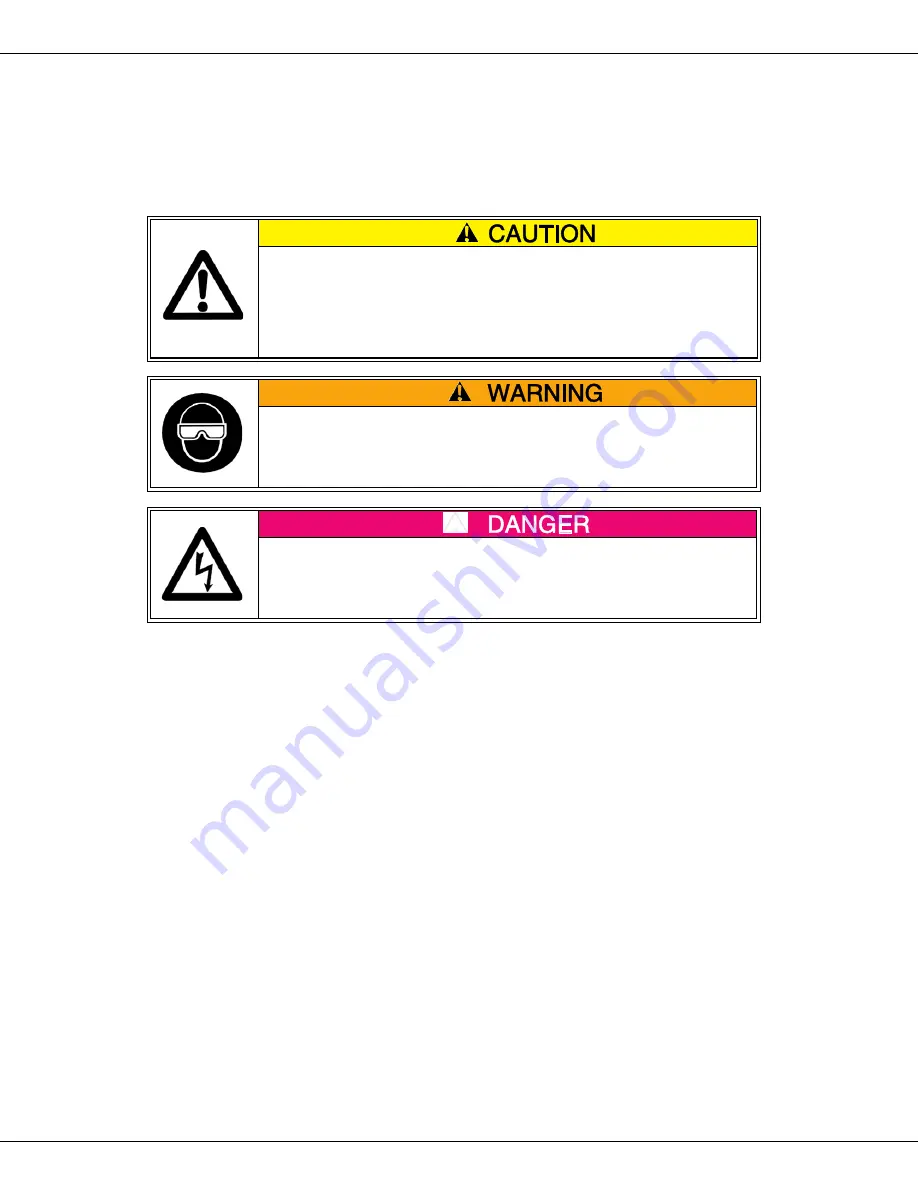
Adequate eye protection must be used when servicing this

equipment to prevent the possibility of injury.

Do NOT immerse the equipment in water.

Unplug your machine before servicing.

LUBRICATION REQUIREMENTS

DRIVE MOTOR

This is a sealed bearing type motor and requires no lubrication.

GAS CONVERSION

1. Disconnect the power supply at the fuse box or breaker.

2. Turn off the gas supply.

3. Refer to drawing number D-5019.

4. Place the kettle in the dump position. Remove the retainer screws. Remove the burner

(Part No. 74558) to expose the burner orifice hood. Replace the main burner hood with the

appropriate part number for the intended type of gas.

A. Part # 74629 (#61) for LP gas.

B. Part # 74630 (#53) for Natural Gas.

5. Replace the pilot burner orifice with the appropriate part number for the intended type of

gas.

Pilot Burner Part No. 74028

A. Part No. 74029 (.011 Dia. Holes) for “LP” Gas.

B. Part No. 74531 (.018 Dia. Holes) for Natural Gas. (“NAT”)

Pilot Burner Part No. 57031

A. Part No. 74029 (.011 Dia. Holes) for "LP” Gas.

B. Part No. 74030 (.023 Dia. Holes) for Natural Gas. (“NAT”)

6. Remove the hex cap on the pressure regulator and position the appropriate end of the red

plug down. “LP” for  Liquefied Petroleum Gas, and “NAT” for Natural Gas.  Replace the

hex cap.  (Instructions continued next page.)

a

Summary of Contents for Mighty-Mite 2035BG

Page 1: ...Mighty Mite Instruction Manual Model 2035BG Bottle Gas Model 2035DC DC Motor Bottle Gas Model 2035NG Natural Gas PartNo 74570 Revised June 1996 Cincinnati OH 45214 2089 USA ...

Page 2: ...GAS SAFETY PRECAUTIONS ...

Page 3: ...ng a location for your new Mighty Mite pay close attention to the installation clear ances The MINIMUM clearance for the sides is 6 inches the MINIMUM top back and frontal clearance is 30 inches This unit is certified for use on combustible surfaces The appliance and its individual shutoff valve must be disconnected from the gas supply piping during pressure testing of that system at pressures gre...

Page 4: ...vation up to 2000 feet above sea level For high altitude operation please contact Gold Medal Engineering for the proper orifice size GAS PRESSURE We have determined that optimum popping results occur when the gas pressure is adequate For LP gas we recommend a pressure setting of 10 inches water column 6 oz per square inch and for Natural Gas 4 inches water column 2 oz per square inch The pressure ...

Page 5: ...justment Cap should be turned to give more or less air A blue flame is desired for optimum heat TO POP POPCORN Turn the main burner on and put oil in the kettle You can let oil heat slightly before adding the popcorn and salt We recommend 14 ounces of popcorn 4 ounces of high quality coconut oil and Flavacol salt to give the best results A good measure of oil and Flavacol is the secret to top qual...

Page 6: ... D 5019 4 Place the kettle in the dump position Remove the retainer screws Remove the burner Part No 74558 to expose the burner orifice hood Replace the main burner hood with the appropriate part number for the intended type of gas A Part 74629 61 for LP gas B Part 74630 53 for Natural Gas 5 Replace the pilot burner orifice with the appropriate part number for the intended type of gas Pilot Burner...

Page 7: ...rt by checking it against the photos illustrations and or the parts list 2 When ordering please include part number part name and quantity desired 3 Please include your model name and machine serial number located on the machine nameplate with your order 4 Address all parts orders to Parts Department Gold Medal Products Co 10700 Medallion Drive Cincinnati Ohio 45241 4807 or place orders at 513 769...

Page 8: ...Mighty Mite ALL MODELS 2035 6 BASO VALVE INFORMATION ...

Page 9: ...Mighty Mite ALL MODELS 2035 7 BASO VALVE INFORMATION continued ...

Page 10: ...Mighty Mite ALL MODELS 2035 8 KETTLE CROSS SECTION ASSEMBLY ...

Page 11: ...per I D 1 16 74554 Thrust Washer Bronze 1 17 86540 Cotter Pin 1 18 74527 Agitator Assembly 1 19 74088 Seal Lid Hold Down Screw 1 20 74117 Flat Washer 8 1 21 74001 Screw Lid Hold Down 1 22 74574 Wing Nut 10 24 Nylon Insert 1 23 74520 Hex Head Bolt 20 x 1 24 47751 Set Screw 20 x 3 16 ADDITIONAL PARTS for Mighty Mite Items not shown 47145 A Scoop 47147 Measure One Cup 47148 Measure 14 Ounce 47660 Gol...

Page 12: ...Mighty Mite ALL MODELS 2035 10 CABINET ASSEMBLY ...

Page 13: ... LP 2 16 74120 Label Lighting Instruction 2 17 89045 Strain Relief T B 3302 2 18 74543 Mighty Mite Pedestal Weld 2 19 74116 Label Ground 2 20 74519 Front Cover Junction Box 2 21 47236 Bushing Snap SB 500 6 2 22 74538 Front Cover Plate 2 24a 74500 Wiring Diagram 120 230 Volt 2 24b 74511 Wiring Diagram 12 Volt 2 25 74119 Label Warning Disc Power 2 26 74551 Extension Shaft Assembly 2 27 74542 Mount P...

Page 14: ...2 45 46566 Spring Pin 1 8 x 7 8 2 46 42070 Set Screw 10 24 x 2 47 47038 Kettle Motor 120V 60 Cycle 2 48 47028 Kettle Motor 230V 50 Cycle 2 49 74576 12 Volt DC Motor 2 50 47202 Switch Motor 120 230 Volt 2 51 47201 Switch On Off 12 VDC 2 52 74147 Screw 8 32 x Rd Hd Ph 2 53 74153 Screw 8 32 x 1 Hex Hd 2 54 74633 Ground Lug ...

Page 15: ...Mighty Mite ALL MODELS 2035 13 ELECTRICAL SCHEMATIC ...

Page 16: ...Mighty Mite ALL MODELS 2035 14 ELECTRICAL SCHEMATIC MODEL 2035DC ONLY ...

Page 17: ... assume for us any other obligation or liability in connection with the sale of said GOLD MEDAL equipment or any part thereof The term Original Purchaser as used in this warranty shall be deemed to mean that person firm association or corporation who was billed by the GOLD MEDAL PRODUCTS COMPANY or their authorized distributor for the equipment THIS WARRANTY HAS NO EFFECT AND IS VOID UNLESS THE OR...

Reviews: