background image

17

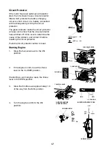
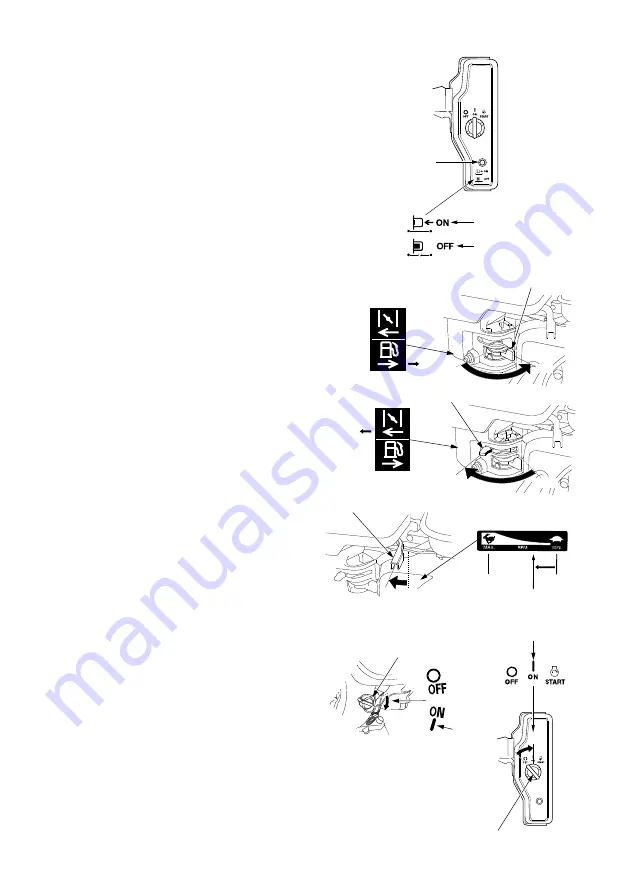
Circuit Protector

If the motor has been optioned with electric 

start, then it will also have a circuit protector 

fitted which protects the battery charging 

circuit. A short circuit, or a battery connected 

with reverse polarity, will trip the circuit 

protector.

The green indicator inside the circuit protector 

will pop out to show that the circuit protector 

has switched off. If this occurs, determine the 

cause of the problem, and correct it before 

resetting the circuit protector.
Push the circuit protector button to reset.

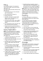
Starting Engine

1.  Move the fuel valve lever to the ON 

position.

2.  If the engine is cold, move the choke 

lever to the CLOSED position.

If restarting a warm engine, leave the choke 

lever in the OPEN position.

3.  Move the throttle lever approximately 1/3 

of the way from the MIN. position.

4. 

Turn the engine switch to the ON 

position.

ENGLISH

3

COMPONENT & CONTROL LOCATIONS

FEATURES

OIL ALERT

®

 SYSTEM (applicable types)

‘‘Oil Alert is a registered trademark in the United States’’

The Oil Alert system is designed to prevent engine damage caused 
by an insufficient amount of oil in the crankcase. Before the oil 
level in the crankcase can fall below a safe limit, the Oil Alert 
system will automatically stop the engine (the engine switch will 
remain in the ON position).

If the engine stops and will not restart, check the engine oil level 
(see page 8) before troubleshooting in other areas.

CIRCUIT PROTECTOR (applicable types)
The circuit protector protects the 
battery charging circuit. A short 
circuit, or a battery connected with 
reverse polarity, will trip the circuit 
protector.

The green indicator inside the circuit 
protector will pop out to show that the 
circuit protector has switched off. If 
this occurs, determine the cause of 
the problem, and correct it before 
resetting the circuit protector.

Push the circuit protector button to 
reset.

FUEL FILLER CAP

FUEL TANK

OIL DRAIN PLUG

ELECTRIC STARTER

(applicable type)

OIL FILLER CAP/DIPSTICK

RECOIL STARTER

AIR CLEANER

MUFFLER

SPARK PLUG

STARTER GRIP

ENGINE CONTROL TYPES

FUEL VALVE LEVER

CHOKE LEVER

EXCEPT ELECTRIC STARTER 

TYPES

ENGINE SWITCH

THROTTLE LEVER

CHOKE LEVER

(air cleaner low profile type)

ELECTRIC STARTER TYPES

ENGINE

SWITCH

CIRCUIT

PROTECTOR

CIRCUIT

PROTECTOR

ON

OFF

37Z4V6100.fm  3 ページ  2018年10月4日 木曜日 午後1時54分

4

ENGLISH

BEFORE OPERATION CHECKS

IS YOUR ENGINE READY TO GO?

For your safety, to ensure compliance with environmental 
regulations, and to maximize the service life of your equipment, it is 
very important to take a few moments before you operate the 
engine to check its condition. Be sure to take care of any problem 
you find, or have your servicing dealer correct it, before you 
operate the engine.

Before beginning your pre-operation checks, be sure the engine is 
level and the engine switch is in the OFF position.

Always check the following items before you start the engine:

Check the General Condition of the Engine

1. Look around and underneath the engine for signs of oil or 

gasoline leaks.

2. Remove any excessive dirt or debris, especially around the 

muffler and recoil starter.

3. Look for signs of damage.

4. Check that all shields and covers are in place, and all nuts, 

bolts, and screws are tightened.

Check the Engine

1. Check the fuel level (see page 8). Starting with a full tank will 

help to eliminate or reduce operating interruptions for refueling.

2. Check the engine oil level (see page 8). Running the engine with 

a low oil level can cause engine damage.

The Oil Alert system (applicable types) will automatically stop 
the engine before the oil level falls below safe limits. However, 
to avoid the inconvenience of an unexpected shutdown, always 
check the engine oil level before startup.

3. Check the reduction case oil level on applicable types (see page 

9). Oil is essential to reduction case operation and long life.

4. Check the air filter element (see page 10). A dirty air filter 

element will restrict air flow to the carburetor, reducing engine 
performance.

5. Check the equipment powered by this engine.

Review the instructions provided with the equipment powered 
by this engine for any precautions and procedures that should 
be followed before engine startup.

OPERATION

SAFE OPERATING PRECAUTIONS

Before operating the engine for the first time, please review the 

SAFETY INFORMATION

 section on page 2 and the

 BEFORE 

OPERATION CHECKS 

on page 4.

Carbon Monoxide Hazards
For your safety, do not operate the engine in an enclosed area such 
as a garage. Your engine’s exhaust contains poisonous carbon 
monoxide gas that can collect rapidly in an enclosed area and 
cause illness or death.

Review the instructions provided with the equipment powered by 
this engine for any safety precautions that should be observed with 
engine startup, shutdown, or operation.

Do not operate the engine on slopes greater than 20° (36%).

STARTING THE ENGINE

1. Move the fuel valve lever to the ON position.

2. To start a cold engine, move the choke lever to the CLOSED 

position.

To restart a warm engine, leave the choke lever in the OPEN 
position.

Some engine applications use a remote-mounted choke control 
rather than the engine-mounted choke lever shown here. Refer 
to the instructions provided by the equipment manufacturer.

Failure to properly maintain this engine, or failing to 
correct a problem before operation, could result in a 
significant malfunction.

Some malfunctions can seriously hurt or kill you.

Always perform a pre-operation inspection before 
each operation and correct any problems.

Exhaust contains poisonous carbon monoxide gas 
that can build up to dangerous levels in closed areas.

Breathing carbon monoxide can cause 
unconsciousness or death.

Never run the engine in a closed, or even partly closed 
area.

FUEL VALVE LEVER

ON

OFF

ON

CHOKE LEVER

CLOSED

CLOSED

OPEN

37Z4V6100.fm  4 ページ  2018年10月4日 木曜日 午後1時54分

ENGLISH

5

3. Move the throttle lever away from the MIN. position, about 1/3 

of the way toward the MAX. position.

Some engine applications use a remote-mounted throttle control 
rather than the engine-mounted throttle lever shown here. Refer 
to the instructions provided by the equipment manufacturer.

4. Turn the engine switch to the ON position.

5. Operate the starter.

RECOIL STARTER:

Pull the starter grip lightly until you feel resistance, then pull 
briskly in the direction of the arrow as shown below. Return the 
starter grip gently.

Do not allow the starter grip to snap back against the engine. 
Return it gently to prevent damage to the starter.

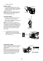
ELECTRIC STARTER (applicable types):

Turn the key to the START position, 
and hold it there until the engine 
starts.

If the engine fails to start within 5 
seconds, release the key, and wait at 
least 10 seconds before operating the 
starter again.

Using the electric starter for more 
than 5 seconds at a time will overheat 
the starter motor and can damage it. 
This type of overheating is not 
covered under warranty.

When the engine starts, release the 
key, allowing it to return to the ON 
position.

6. If the choke lever was moved to the CLOSED position to start 

the engine, gradually move it to the OPEN position as the 
engine warms up.

THROTTLE LEVER

MAX.

MIN.

1/3 POSITION

MIN.

EXCEPT ELECTRIC 
STARTER TYPES

ELECTRIC STARTER TYPES

ON

ENGINE SWITCH

ON

ENGINE SWITCH

ON

ON

STARTER GRIP

Direction to pull

START

START

ENGINE SWITCH

(applicable types)

OPEN

CHOKE LEVER

CLOSED

OPEN

37Z4V6100.fm    ページ  2018年10月4日 木曜日 午後1時54分

ENGLISH

5

3. Move the throttle lever away from the MIN. position, about 1/3 

of the way toward the MAX. position.

Some engine applications use a remote-mounted throttle control 
rather than the engine-mounted throttle lever shown here. Refer 
to the instructions provided by the equipment manufacturer.

4. Turn the engine switch to the ON position.

5. Operate the starter.

RECOIL STARTER:

Pull the starter grip lightly until you feel resistance, then pull 
briskly in the direction of the arrow as shown below. Return the 
starter grip gently.

Do not allow the starter grip to snap back against the engine. 
Return it gently to prevent damage to the starter.

ELECTRIC STARTER (applicable types):

Turn the key to the START position, 
and hold it there until the engine 
starts.

If the engine fails to start within 5 
seconds, release the key, and wait at 
least 10 seconds before operating the 
starter again.

Using the electric starter for more 
than 5 seconds at a time will overheat 
the starter motor and can damage it. 
This type of overheating is not 
covered under warranty.

When the engine starts, release the 
key, allowing it to return to the ON 
position.

6. If the choke lever was moved to the CLOSED position to start 

the engine, gradually move it to the OPEN position as the 
engine warms up.

THROTTLE LEVER

MAX.

MIN.

1/3 POSITION

MIN.

EXCEPT ELECTRIC 
STARTER TYPES

ELECTRIC STARTER TYPES

ON

ENGINE SWITCH

ON

ENGINE SWITCH

ON

ON

STARTER GRIP

Direction to pull

START

START

ENGINE SWITCH

(applicable types)

OPEN

CHOKE LEVER

CLOSED

OPEN

37Z4V6100.fm    ページ  2018年10月4日 木曜日 午後1時54分

Summary of Contents for Prairie Compact 400L

Page 1: ...Prairie Compact 400 600L Operator s Parts Manual GA8701149 REV0 JUN 2020 ...

Page 2: ...Assembly 37 Suction Filter Body 38 Tank Assembly 39 Tank Brackets 40 Tank Drain 41 Tank Mounting 42 Plumbing Schematic 43 Contact Goldacres 1 3 Morang Crescent Mitchell Park Vic 3355 P 03 5342 6399 F 03 5342 6308 info goldacres com au Disclaimer Any advice or recommendations given by Goldacres Goldacres dealers or employees is given in good faith and provided based on the best information availabl...

Page 3: ...acres not only produce Australia s finest range of spraying equipment we also keenly value the unique relationship we enjoy with owners of our equipment We are pleased to welcome you as a Goldacres owner and look forward to making your spray applications as efficient as possible Please use this comprehensive resource to gain a full understanding of your equipment and don t hesitate to contact your...

Page 4: ... successful performance Operators working outside these limitations do so at their own risk unless specific advice has been sought from and provided by Goldacres in writing Inspect the equipment thoroughly for damage and wear before operation Always read and follow the chemical manufacturer s guidelines for safe application as per the chemical label Particular attention should be given to the reco...

Page 5: ... are tightened and secured before operation Always ensure that the boom is securely supported when travelling Where fitted care should be taken to never overfill the diaphragm pump with oil or operate at speeds exceeding 540 rpm Do not exceed the maximum spraying pressure of 8 Bar Dangers Check area to be sprayed for overhead powerlines Contact between the machine and powerlines can result in seri...

Page 6: ...two main risks are that this equipment may easily cut through the lines or the local heat generated near the lines may cause them to rupture Ensure that all fittings and lines are fully tightly secured before re pressurizing after repairs Lifting Machine Before raising the machine off the ground Ensure that the boom is in its closed position Park up on a flat level and firm area Empty the spray ta...

Page 7: ...s prior to operation of this equipment as a spray unit Safety Decals Understanding safety decals and their purpose assists in the safe operation of your sprayer Safety decals are there for your protection and it is the responsibility of the owner operator to replace damaged and or missing safety decals Regularly review safety decals with operators It is very important to ensure that all new machin...

Page 8: ... housing Hydraulics Axle frame only Shockers and dampeners Wire cables Springs Drive chains Wheel bearings Failure caused by lack of lubrication not covered Warranty Exclusions Pump diaphragms Pump Seals Pump check valves Pump O rings Filters and filter screens Filter O rings Chemical Hoses Solenoid Diaphragms Hand Gun lance or wand seals and O rings Consumables chemicals fuels Items controlled by...

Page 9: ...anship or materials used under normal use and service conditions The Warranty is not transferable The owner is responsible for the performance of regular maintenance and service as specified in the owner s operators manual applicable to the product Failure to follow regular maintenance as advised may invalidate the warranty The owner must provide the Goldacres Dealer with prompt written notice of ...

Page 10: ...rchaser is entitled to at law which cannot be excluded by these terms and conditions and in all other cases b making good any defects by repairing the same or at Goldacres option by replacement within a period not exceeding either 1000 hours or twelve calendar months whichever comes first after the Goods have been dispatched provided that i the defects have arisen solely from faulty materials or w...

Page 11: ...h ranking whether by act or omission 3 The Purchaser acknowledges that it has received value as at the date of first delivery of the Goods and has not agreed to postpone the time for attachment of the security interest as defined in the PPSA granted to Goldacres under these terms and conditions 4 The Purchaser will execute documents and do such further acts as may be required by Goldacres to regis...

Page 12: ...an be a variance in the overall dimensions of the tank which in turn results in variations to the tank capacity For this reason calibration markings should be used as a guide only Filtration Filtration is a critical part of the sprayer s performance The pump assembly is fitted with an inline suction strainer It is important that the strainer is cleaned out regularly Pump The pump is critical to an...

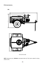
Page 13: ...hey may be subject to change without notice Dimensions 2391 1190 1519 THIS DRAWING REMAINS THE PRO OF GOLDACRES TRADING PTY LTD SUBJECT OF COPYRIGHT UNLESS OTHERWISE SPEC DIMENSIONS ARE IN MILLIM UNLESS OTHERWISE SPEC 0 1 ANGULAR 0 0 0 5 0 00 0 25 F E D C B A 1 1 2 2 3 3 4 4 400L ...

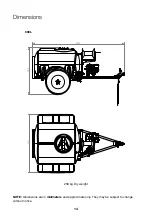
Page 14: ...may be subject to change without notice Dimensions 600L 1519 1208 2390 THIS DRAWING REMAINS THE PROP OF GOLDACRES TRADING PTY LTD A SUBJECT OF COPYRIGHT UNLESS OTHERWISE SPECIF DIMENSIONS ARE IN MILLIME UNLESS OTHERWISE SPECIF 0 1 ANGULAR 0 0 0 5 0 00 0 25 F E D C B A 1 1 2 2 3 3 4 4 ...

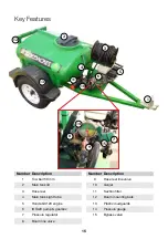
Page 15: ...tank lid 3 Hose reel 4 Main tank sight tube 5 Honda GX120 engine 6 IOTA20 pump gearbox 7 Pressure regulator 8 Boom line valve Number Description 9 Hose reel line valve 10 Gunjet 11 Suction filter 12 Boom mounting bars 13 Plastic mudguards 14 Pressure gauge 15 Bypass valve 7 9 8 14 15 ...

Page 16: ... owner s manual supplied or find a copy online Engine Safety Understand the of all controls and learn how to stop the engine quickly in case of emergency Do not allow children to operate the engine Keep children and pets away from the area of operation Your engine s exhaust emits poisonous carbon monoxide Do not run the engine without adequate ventilation and never run the engine indoors The engin...

Page 17: ...iously hurt or kill you Always perform a pre operation inspection before each operation and correct any problems Exhaust contains poisonous carbon monoxide gas that can build up to dangerous levels in closed areas Breathing carbon monoxide can cause unconsciousness or death Never run the engine in a closed or even partly closed area FUEL VALVE LEVER ON OFF ON CHOKE LEVER CLOSED CLOSED OPEN 4 ENGLI...

Page 18: ... the starter grip gently Do not allow the starter grip to snap back against the engine Return it gently to prevent damage to the starter ELECTRIC STARTER applicable types Turn the key to the START position and hold it there until the engine starts If the engine fails to start within 5 seconds release the key and wait at least 10 seconds before operating the starter again Using the electric starter...

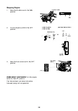
Page 19: ...X 6 ENGLISH procedure Refer to the instructions provided by the equipment manufacturer 1 Move the throttle lever to the MIN position Some engine applications use a remote mounted throttle control rather than the engine mounted throttle lever shown here 2 Turn the engine switch to the OFF position 3 Move the fuel valve lever to the OFF position Some engine rather than th the instructio For engine s...

Page 20: ...amage Ensure that the pump can be turned over by hand before starting 2 Inspect all hoses to make sure they are the correct size fitted securely and that there is no restriction or leaking 3 Make sure that guards and covers are fitted correctly to prevent accidental injury 4 Make sure the strainer in the suction filter is clean and correctly installed 5 Change the pump oil after the first 50 hours...

Page 21: ...the pump Incorrect air damper chamber pressure Running pump at speeds greater than 600 RPM Exceeding the 290 PSI pressure limit of the pump Failure to wash chemicals from pump after use Incompatibility of the diaphragm material and the chemicals used DIAPHRAGM REPLACEMENT When diaphragms require replacement it is normal practice to replace the air damper diaphragm at the same time 1 Flush pump wit...

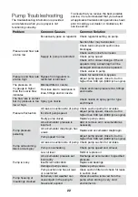
Page 22: ...es fittings and or nozzle The flow rate is correct but my pressure is too low or high Spray gun nozzle Check nozzle on spray gun for type and fitment Pressure fluctuation Air leak on suction side of pump Check suction pump for air leaks Incorrect pump speed Adjust pump speed close to but no higher than 600 rpm 3000 rpm engine Faulty pump valves Replace pump valves Pump pressure pulsating Air accum...

Page 23: ...hemical residue from the pump SAFETY SHUT OFF VALVE The safety shut off valve enables the filter bowl to be removed while automatically shutting off the supply line to the filter As the filter bowl is removed together with the bowl cap the valve plunger seats so as to seal off the filter from the supply line Replacing the filter bowl unseats the valve plunger and thus opens the supply line to the ...

Page 24: ...he nozzle pattern by rotating the nozzle in the appropriate direction as required 7 Adjust the pressure regulator to raise or lower the spray rate to suit application This will ensure even and consistent coverage of the target Do not exceed 290 PSI 20 BAR NOTE Refer to your chemical manufacturer s information for determining appropriate spray rates or consult an agronomist for further help Agitati...

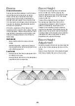
Page 25: ...ays ensure that there is adequate room for the boom to open Always ensure that the boom is adequately supported when transporting Boom Height The standard nozzle spacing on Goldacres booms is 500 mm For this spacing the optimum height the boom should be from the object to be sprayed with a 110 fan angle nozzle is 500 mm There will be adequate spray coverage if the nozzles are higher than this but ...

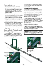
Page 26: ...e boom wing angle by removing one set of adjuster bolts at a time and reinserting them into another hole position Fold spring adjustment holes Boom wing angle stopper bolt Boom wing angle adjustment bolts The wings should be made parallel with the centre section Re tighten the adjuster bolts once complete Horizontal Angle Adjustment The boom horizontal angle is determined by the stopper bolt posit...

Page 27: ... all fasteners such as bolts nuts washers and any zinc plated components G15 anti corrosion spray should also be applied to the sprayer pre and post season The amount of corrosion protection necessary will ultimately depend on local and operating conditions Frequency Maintenance Tasks 8 Hour Check pump oil level condition 8 Hour Check tyre pressure 8 Hour Check wheel nuts are torqued correctly to ...

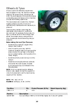
Page 28: ...the tyre pressure Determining Correct Tyre Pressure Determine the maximum weight of the sprayer when loaded Allow for each tyre to carry half the maximum loaded weight of the sprayer this does not allow for any load on the tractor pull or cyclical loading which provides for a safety margin Determine what tyre size and ply is on the sprayer Determine what appropriate tyre pressure will provide the ...

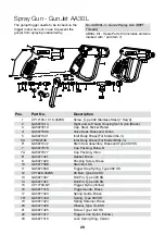
Page 29: ...or Model 30L 5A CPB22136 Inlet Body Brass For Model B30L 6 GA5077442 Stem Sub Assembly Brass and Type 302 SS 7 GA5077376 Cup Packing Buna N 7A GA5077377 Cup Packing Viton 8 GA5077421 Gasket Brass 9 GA5077420 Packing Screw Brass 10 GA5077588 Stem Nut SS 11 GA5077589 Trigger Stop Spring Type 302 SS 12 CP7622 302SS 6 Burr Type 302 SS 13 GA5077407 Roll Pin Type 420 SS 14 GA5077427 Roll Pin Type 420 SS...

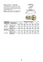
Page 30: ...p No Performance Liquid Pressure bar 1 5 2 3 4 A B A B A B A B GA8100370 Standard Capacity l min 0 79 2 61 0 98 3 18 1 14 3 67 1 40 4 54 Spray angle º 71 75 77 78 Max throw m 1 2 11 6 1 2 12 8 1 2 13 3 1 2 13 0 GA8100377 Capacity l min 0 98 3 14 1 21 3 79 1 40 4 54 1 70 5 30 Spray angle º 71 75 78 79 Max throw m 1 2 11 7 1 40 13 0 1 5 13 6 1 5 13 2 GA8100371 Capacity l min 1 17 3 71 1 40 4 54 1 63...

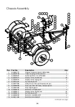
Page 31: ... HD 24 12 GA5000141 Nut M10 Nyloc ZP 12 13 GA5000355 Bolt M12 x 80 GR8 8 ZP 2 14 GA5011489 Bolt M8 x 60 GR8 8 ZP 1 2 8 23 29 32 25 9 3 4 4 5 6 7 13 4 4 6 24 4 4 6 22 11 11 12 26 28 31 27 4 30 10 11 11 12 1 19 20 21 14 15 16 17 16 18 NOTE APPLY LOCTITE 243 ONTO ALL THREADS ITEM P 1 2 3 4 5 6 7 8 9 10 11 12 13 14 15 16 17 18 19 20 21 22 23 24 25 26 27 28 29 30 31 32 MATERIAL THIS DRAWING REMAINS THE...

Page 32: ... linch pin 8 OD x 60 mm long 1 22 GA5065455 Bolt M10 x 30 GR8 8 ZP 8 23 GA5024460 Trailer mudguard to suit 14 Tyres Plastic 2 24 GA5011263 Bolt M12 x 90 GR8 8 ZP 2 25 GA5078435 Hub Axle Hub face face 1311mm 1 26 GA5078436 Axle fish plate 4 Hole 45mm x 40mm 2 27 GA5078439 U Bolt 40mm x 127mm 4 28 GA5078440 Slipper spring 5 Leaf 45mm with Nylon bush 2 29 GA5017801 Tyre and Wheel 185R14 14 x6 White S...

Page 33: ... 4 Female BSPT 1 7 GA5077716 Hose Barb Elbow 90 degree 3 4 male thread x 1 hose Ban o 1 8 GA5001681 Hose clamp 1 SS 20 32 12W 1 THIS DRAWING REMAINS OF GOLDACRES TRADING SUBJECT OF COPY UNLESS OTHERWISE DIMENSIONS ARE IN UNLESS OTHERWISE 0 1 ANGU 0 0 0 5 0 00 0 25 D C B A 1 1 2 2 3 3 Pos Part No Description Qty 1 GA4906752 Pump engine Honda GX120 6 1 reduction Iota 20 1 2 GA2000059 Gauge Pressure ...

Page 34: ...S TRADING PTY L SUBJECT OF COPYRIGH UNLESS OTHERWISE SPE DIMENSIONS ARE IN MILL UNLESS OTHERWISE SPE 0 1 ANGULA 0 0 0 5 0 00 0 25 D C B A 1 1 2 2 3 3 Pos Part No Description Qty 1 GA5011475 Bolt M8 x 30 GR8 8 ZP 4 2 GA5004085 Bolt M8 x 20 GR8 8 ZP 3 3 GA5052590 Nut M8 Nyloc SS 4 4 GA5003643 Washer 8mm Flat SS HD 11 ...

Page 35: ... GA5076514 GA5076548 GA5076548 GA5076548 GA5076065 GA5076440 GA5077089 GA5076062 GA5076066 GA5078415 GA5078415 GA5075980 GA5076451 GA5076545 GA5075985 GA5076548 GA5075802 GA5076068 GA5075711 GA5075990 GA5076507 GA5076068 GA5075990 GA5078269 GA5076065 GA5075990 GA5075991 GA5076065 GA5076065 GA5024195 GA5075750 Pump IOTA 20 ...

Page 36: ...on box 5 1 to suit a GX120 Honda engine with a 3 4 shaft GA5076514 Plug 2 GA5075800 Seal Rubber 13 ID x 19 OD x 1 5 mm Suit diaphragm pump oil plug 2 GA5078263 Gasket Iota 20 1 GA5078464 Gear shaft Motor to gear box Iota 20 3 4 1 GA5075629 Oil Seal D17 x 35 x 7 mm 1 GA5075731 Ball Bearing D15 x 35 x 11 mm 1 GA5076571 Hex Screw 5 16 x 1 UNF 4 GA5076516 Oil Plug Gasket 1 ...

Page 37: ... ITEM PART NUMBER DESCRIPTION QTY 1 GA2000106 Suction Filter 1 1 2 50 Mesh 1 1 2 BSP Male Threads Geoline 1 2 GA5001681 Hose clamp 1 SS 20 32 12W 2 3 GA5076604 Fly nut 1 1 2 Arag 2002060 2 4 GA5076036 Hose barb Straight 1 1 2 ly nut end x 1 hose barb Udor 2 5 GA5077679 O ring 30 x 3 mm G10061 2 TITLE MATERIAL DRAWN BY JAMES MARTIN NEALHARVEY MODEL EDITED BY 27 06 2018 SURFACE FINISH UNLESS OTHERWI...

Page 38: ... 167 mm length Suit Geoline Filter GA2000106 O rings GA5024290 are not included 1 GA5024290 O ring Suit filter mesh 2 5 C00201009 Bowl Suction filter 1 1 2 Geoline C00201009 1 6 K00100001 Drain plug Suction filter 1 1 2 Geoline K00100001 1 1 3 4 5 6 2 ITEM NO 1 2 3 4 5 6 MATERIA THIS DRAWING REMAINS THE PROPERTY OF GOLDACRES TRADING PTY LTD AND IS SUBJECT OF COPYRIGHT SURFACE WEIGHT UNLESS OTHERWI...

Page 39: ...ER DRILLING THE TANK TO SUIT 2 INCH 581 SCREW FITTI DRILLING TH BACK OF THE E TANK TO SUIT 6 5 1 4 10 5 3 6 5 ITEM PART NUMBER DESCRIPTION 1 GA5023135 600lt Cartage Spray tank and lid 2 GA5078336 Lid Hinged Black plastic 355mm 35604 3 GA5077708 Hose barb Elbow 90 degr thread x 1 2 hose Ban o 4 GA5077704 Hose barb Elbow 90 degr thread x 3 4 hose 5 GA5000469 Hose clamp 1 2 SS 12 6 GA5077710 Hose bar...

Page 40: ... THE TANK IS TO BE USED THERE IS ADJUSTMENT WITH BOTH THE VERTICAL PIECE AND THE TANK SUPPORTS BOTH THE FIXED AND UNFIXED SUPPORTS 6 1 2 3 3 4 8 THIS DRAWING REMAINS THE PRO OF GOLDACRES TRADING PTY LTD SUBJECT OF COPYRIGHT UNLESS OTHERWISE SPEC DIMENSIONS ARE IN MILLIM UNLESS OTHERWISE SPEC 0 1 ANGULAR 0 0 0 5 0 00 0 25 F E D C B A 1 1 2 2 3 3 4 4 1 3 4 REAR MOUNTING LEFT SIDE 2 3 4 1 3 ITEM PART...

Page 41: ...1 1 GA5018309 Valve Ball 12mm 1 2 female Lever handle Brass 1 2 GA5077704 Hose barb Elbow 90 degree 1 2 male thread x 3 4 hose 1 3 GA5001741 Washer 20mm Flat SS HD 2 4 F70565A Sump drain mounting plate 1 5 GA5077707 Hose barb 1 2 male thread x 3 4 hose 1 6 GA5002077 Key ring 25mm SS 1 6 5 3 4 3 1 2 ITEM PART NUMBER DESCRIPTION QTY 1 GA5018309 VALVE BALL 12mm 1 2 FEMALE LEVER HANDLE BRASS 1 2 GA507...

Page 42: ...sump and lid 1 GA5011223 Bolt M12 x 200 GR 8 8 ZP 4 GA5000577 Washer 12mm Flat SS HD 8 GA5017673 Washer 1 2 High Tensile 8 GA5012461 Nut M12 Nyloc ZP 4 THIS DRAWING REMAI OF GOLDACRES TRADIN SUBJECT OF C UNLESS OTHERW DIMENSIONS ARE I UNLESS OTHERW 0 1 AN 0 0 0 5 0 00 0 25 1 2 3 Pos Part No Description Qty 1 GA8500016 Tank 400L Green Cartage with sump lid 1 GA5023135 Tank 600L Green Cartage with s...

Page 43: ...3 Plumbing Schematic GA6500016 plumbing dwg J Rowsell 1 2 P Suction Filter GA2000106 Honda GX120 Motor Iota 20 Pump GA5077765 Reduction Gearbox GA5072295 30m Hose Reel 10mm Hose 1 S 1 S 3 4 P 1 2 P 1 2 P ...

Page 44: ...44 1 3 Morang Crescent Mitchell Park Vic 3355 P 03 5342 6399 F 03 5342 6308 info goldacres com au goldacres com au ...

Reviews: