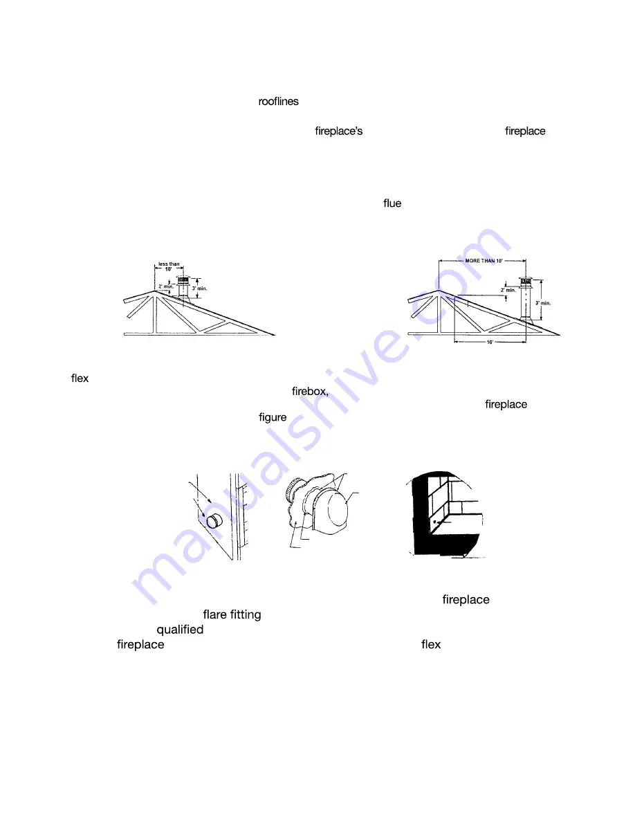
Installing Chimney/Vent System Continued
3.
The 10' Rule of Thumb is a guide for calculating chimney height that works under most conditions. However,
many factors can cause the need for additional chimney height beyond what 10' Rule of Thumb would indicate.
Topographical factors can cause high-pressure zones, which prevent a chimney from drawing. This can occur if
the house is located in a low-lying area, in a valley or near the base of a cliff or hillside. The same situation can
occur if the chimney is near other steep
or tall buildings. Areas with high winds also frequently require
higher than normal chimneys.
Certain styles of architecture tend to interfere with a
draw. If the room in which the
is located
has a very high ceiling, smoke may enter the room unless the chimney is terminated at a level higher than that
of the ceiling, even if the 10' Rule of Thumb indicates a shorter chimney height.
Note:
Installations which will not allow the 10' rule to be followed must be submitted to Golden Blount Inc. for
approval. 1-800-833-1139.
Warning!
This gas appliance must not be connected to a chimney
serving a separate solid-fuel
burning appliance.
Note: A draft hood is installed and is in the same atmospheric pressure zone as the combustion air inlet to the
appliance and is located so that the relief opening is accessible for checking vent operation.
9
Installing Outside Air Kit
Models LFP4218/6018 are supplied with the component parts for outside combustion with the exception of the
4"
duct. It is recommended that the outside air system be used whenever possible. Connect 4" Class-1
Flex duct or Metal Vent to duct collar on side of
run duct to fresh air source and terminate using duct
termination cap. The Outside air can be opened by pulling control knob toward front of
and
closed
one on each side.
by pushing towards rear (Refer to
9.1). NOTE: Model LFP6018 supplied with two duct collars,
CONTROL
KNOB
DUCT
TERMINATION
LEFT SIDE LFP4218
LEFT AND RIGHT
LFP6018
RAIN CAP
CAULKING
WALL
OUTER
CASING
DUCT
COLLAR
TWO
SUPPLIED
WITH
LFP6018
Figure 9.1
Connecting the Gas Line
Consult local building codes before gas line installation. This gas
is designed
to accept a 3/8" male
attached to a 1/2" supply line. Have the gas line
installed by a
service person in accordance with all building codes. Install gas
line to
on the right side attaching gas line to the gas
line inside the control
box accessed by opening the control box door.
f i r e - p a r t s . c o m
Summary of Contents for LFP4218
Page 16: ...16 fire parts com ...
Page 17: ...17 fire parts com ...
Page 19: ...19 Inc fire parts com ...


