23
Install Elevator Horn & Push-Rod:
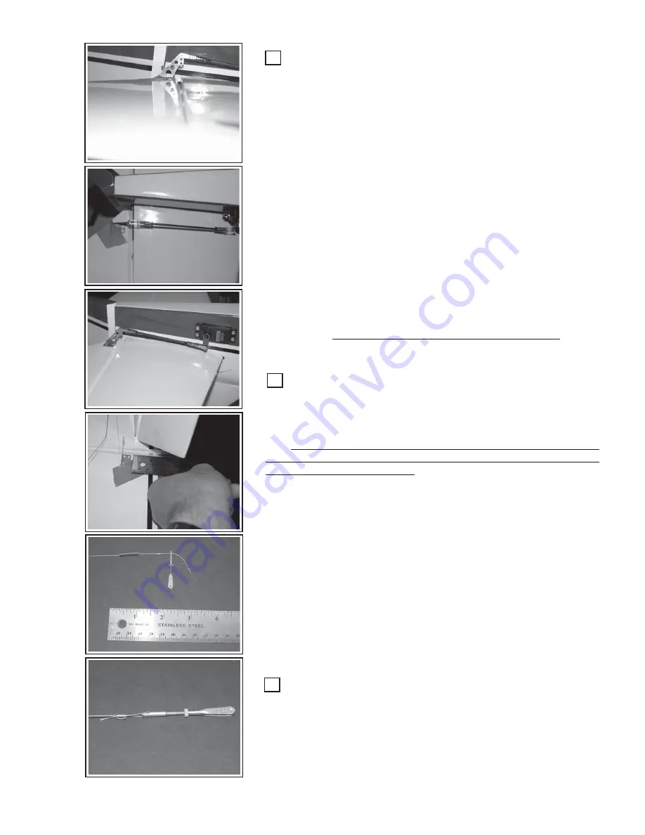
Like the aileron horn alignment , the elevator horn requires two
alignments, 1) With the elevator hinge line and 2) in straight line with the
elevator servo-arm. Again, using the elevator push-rod and a piece of
blue masking tape, may help you align the elevator horn. Be sure the
elevator and the servo-arm are both in the neutral position.
Mark and drill pilot holes in the four locations to mount the elevator
control horn. Use a 1/16” bit and drill to about 1/8” depth. Generously
treat the holes and surrounding area with thin CA glue. Allow to dry and
attach the control horn with the screws provided.
Attach the push-rod and adjust for mechanical center. Tighten the
locking nuts up to the clevis base and apply drop of locktite® to the push-
rod threads just behind the locking nuts. Be sure the clevis retainer springs
are in place and secure.
Check the servo-arm movement and the corresponding elevator
movement. Throws will be discussed later.
Adjusting for the greatest “
volume”
of movement is done by attach-
ing the push-rod close to the pivot point of the elevator servo and at the
top point of the control horn.
For greater sensitivity and control throw, do just the opposite. At-
tach the push-rod at the tip of the servo-arm and at the bottom of the
control horn.
Take care with this high-sensitivity arrangement.
Unless
you are a highly experienced pilot, this arrangement may be too sensi-
tive for you and cause you to crash. (See Control Throws)
Install the Rudder Control-Horns
(2 ea)
:
Dress the pull-pull cables such that there is an equal length of cable
feeding through to each side of the rudder. Cut the loop in the cable at
the tail so that you now have two distinct cables. Remember that these
cables are to cross each other in the fuselage.
Take note that the two rudder control-horns are set at slightly differ-
ent heights on each side of the rudder to prevent the mounting screws
from interfering with each other.
Using a ruler, measure 2-3/4” up from the bottom of the rudder to
the bottom of the rudder control-horn to set the position of the control-
horn on one side of the rudder.
Measure 2-7/8” up from the bottom of the rudder to the bottom of
the control-horn to set the position of the rudder control-horn on the op-
posite side of the rudder.
The rudder horns requires two alignments, 1) With the rudder hinge
line, and 2) in height above the bottom of the rudder as described above.
Again, using a piece of blue masking tape, may help you align hold the
rudder horns in place while marking to drill pilot holes.
Mark and drill pilot holes in the four locations to mount the rudder
control horn. Use a 1/16” bit and drill to about 1/8” depth. Generously
treat the holes and surrounding area with thin CA glue. Allow to dry and
attach the control horn. Adding a bit of medium CA glue to the hole prior
to inserting the screw will help secure the screw.
Build the Pull-Pull Cable System:
Starting at the rudder end of the cable, thread the cable through the
copper clamp-tube and through the threaded clevis-rod. Loop back into
the clamp-tube and then re-loop back around and through the tube as
shown. Note there is an optional piece of shrink-tubing on the cable just
to “pretty-up” the final assembly. You will need a pair of needle nose
pliers to make the final cable penetration of the tube. Arrange the tube to
be 1/4” to 3/8” away form the clevis-rod and tighten up the cable loops.


