26
Install Fuel Tank:
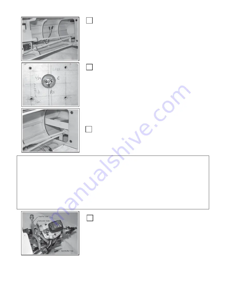
Slide the fuel tank into the forward fuselage area such that the front
tubes protrude through the firewall in the round hole provided. Orient
small pieces of foam rubber between the tank sides and fuselage former
(F2) to cushion the tank from vibration. (Window sealing foam, that comes
in various width, adhesive backed strips, is available at your local hard-
ware store. Glue the strips to the inside hole in former F2 and then slide
in the tank.
Seal the Tank at Fuselage:
You should have previously coated the inside of the firewall tank
opening with 30-minute epoxy to protect the hole edges from the effects
of fuel. Using RTV-Silicon sealer/caulk, seal the joint between the fuel
tank the firewall. If you use your finger, wet the tip of your finger to
minimize the silicon from sticking to your finger. Form a bead of sealant
all the way around the tank and firewall intersection.
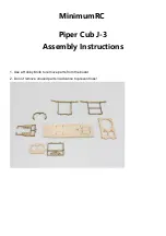
Reattach the engine mount using locktite® on the mounting bolt
threads and securely fasten down. Note on the picture (left), the horizon-
tal lines just inside of the mounting holes are the placement of the inside
edge of the mounting rail and matches your engine crankcase width plus
~ 0.05” (~3/64).
Step 11: Install the Engine:
The following illustrations will show the installation of a OS-91FS ® 4/stroke engine.
You may choose to install the engine of your choice. The process will be similar where the
biggest differences will be the throttle push-rod routing and muffler installation. You will
need: 1) engine, 2) mounting bolts (# 6-40 minimum), 3) locknuts, 4) screwdrivers and/or
nut drivers, 5) Needlenose pliers, 6) Plastic, throttle push-rods, 7) CA glue - medium, 8)
fuel tubing,
Brace Fuel Tank
:
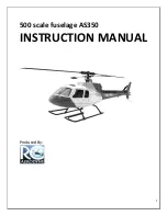
Using a scrap piece of balsa or lite-ply, form a brace as shown left to
prevent the fuel tank from sliding backwards. Many different brace ar-
rangements will work. The one shown (left) is easy and effective. Wedge
a piece of foam rubber between the brace and the back of the tank.
Install Fuel Tubing to Engine:
Reattach the engine. Only two bolts in opposite corners are neces-
sary at this time, as you will shortly remove the engine to install the cowl.
Cut three pieces of silicon fuel tubing at the correct length to reach from
the fuel tank ports to their respective functional locations on the engine:
1) Carburetor
2) Vent/Muffler
3) Filler cap (optional), Notice that an optional fuel filler line has
been installed and terminated with a “filler-cap”. (Available at
your local hobby store or at the GSRC website .....
http:// www.goldenskiesrc.com)
You do not need to attach the tubing to the engine, as you will be
removing the engine to install the cowl. (Shown attached for clarity)


