Buzzaround XL_SG_REVA_100711
2
Table of Contents
Nomenclature and Contact Information..................................................................................................................... 3
ABOUT THE BUZZAROUND XL SERVICE GUIDE........................................................................................... 4
Buzzaround XL Components........………………………………………………………………………………...4-9
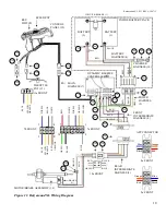
Wiring Diagram...............…………………………………………………………………………………………. 10
SCENARIO 1: Turn the key to the on position and no power....................................……………………………. 11
SCENARIO 2: Batteries will not charge..........................………………………………………………………….12
BEEP CODES......……………………………………………………………………………………………... 13-18
BEEP CODE #1 – Batteries Low (Scooter may drive slowly).......………………………………………………. 13
BEEP CODE #2 – Batteries Low (Scooter will not operate).......………………………………………………… 13
BEEP CODE #3 - High Battery Voltage.....………………………………………………………………………. 13
BEEP CODE #4 - Current Limit Timeout.........………………………………………………………………..13-14
BEEP CODE #5 - Brake Fault.....……………………………………………………………………………... 14-15
BEEP CODE #6 - Paddle Fault (out of neutral)..... ………………………………………………………………. 15
BEEP CODE #7 - Paddle Fault/Speed Control Fault (voltage error).....……………………………………… 16-17
BEEP CODE #8 - Motor Voltage Fault (Open/Shorted).....…………………………………………………... 17-18
BEEP CODE #9 - Controller Fault.....……………………………………………………………………………. 18
BUZZAROUND XL REPLACEMENT INSTRUCTIONS……………………………………………………… 19
Drive Wheel.....…………………………………………………………………………………………………… 19
Drive Train....……………………………………………………………………………………………………... 19
Throttle Pot........……………………………………………………………………………………………….. 19-20
Battery.........………………………………………………………………………………………………………. 21
Circuit Breaker.....………………………………………………………………………………………………… 21
Battery Harness Fuse....………………………………………………………………………………………….... 21
Controller........……………………………………………………………………………………………………. 21
Main Harness.....………………………………………………………………………………………………….. 22
Control Panel.....………………………………………………………………………………………………….. 23
Brake....…………………………………………………………………………………………………………… 23
Front Intermediate Harness……………………………………………………………………………………….. 24
Rear Intermediate Harness………………………………………………………………………………………... 25
APPENDIX A - HOW TO USE A VOLTMETER....……………………………………………………………. 26
APPENDIX B - HOW TO USE AN OHM METER....…………………………………………………………... 27
APPENDIX C - WIRING DIAGRAMS....…………………………………………………………………… 28-31
APPENDIX D - TROUBLESHOOTING FLOW CHARTS....………………………………………………. 32-43
ILLUSTRATED PARTS BREAKDOWN
GB116................................................................................................................................................................. 44-68
GB146…………………………………………………………………………………………………………. 69-93


