Buzzaround XL_SG_REVA_100711
6
1
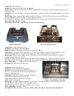
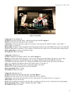
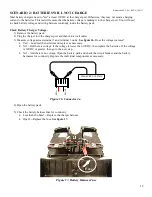
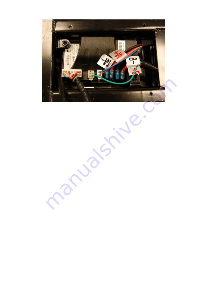
Figure 5. Controller
Component:
Power Harness (5)
Location:
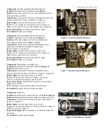
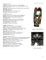
Mounted to the front frame - under the battery pack.
See #5 on figure 4.
Function:
Connects the battery pack to the controller.
Connections:
Connects to the battery pack (4a). Connects to the controller 5b (inhibit), 5c (Bat -), and 5d (Bat +).
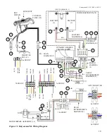
Refer to figure 11 on page 10.
Failure Signs:
Charger is on and connected to the battery pack and the scooter runs (inhibit). No power to the controller.
Tests:
Test harnesses for continuity. Check connectors. Make sure the contacts are not corroded and are seated properly.
Expected Readings:
Continuity (less than 10 ohms).
Serviceable:
Replace as necessary.
Component:
Controller (6)
Location:
Underside of the frame, inside cover.
See #1 on figure 5.
Function:
Controls and monitors the system. Uses a series of beeps when something in the system is out of range.
Connections:
Connected to the main harness (7a), the charger inhibit (5b), the motor brake (8b), the front
intermediate motor harness negative (8c), the front intermediate motor harness positive (8d), the power harness
negative (5c) and the power harness positive (5d). Refer to figure 11 on page 10.
Failure Signs:
Beep Code #9. No power to the control panel or the motor.
Tests:
Test for voltage coming into and out of the controller.
Expected readings:
Battery voltage.
Serviceable:
Replace as necessary.
Component:
Main Harness (7)
Location:
Inside the tiller and under the frame.
See #2 on figure 5.
Function:
Provides connectivity for the tiller components and the controller.
Connections:
Connected to the controller (6) and the control panel (12b). Refer to figure 11 on page 10.
Failure Signs:
Scooter will not run.
Tests:
Test for voltage and continuity. Check connectors. Make sure the pins are not corroded and are seated properly.
Expected readings:
Battery voltage. Continuity (less than 10 ohms).
Serviceable:
Replace as necessary.
1
2


