background image

Alanté Sport_GP205CC/SS_Owner’s Manual                                                                                               Rev C_102714 

                               VII. OPERATION 


DIAGNOSTICS/TROUBLESHOOTING                                                                                       

Below are a list of trouble-shooting actions. Try to use this list before you contact your                  
Golden Technologies representative. Go to the number on the list which matches the 
number of flashing LEDs and follow the instructions. If the problem persists after you made 

the checks described, contact your Golden Technologies representative for further 
assistance. 
  

1 LED 

The battery needs charging or there is a bad connection to the battery. Check the 

connections to the battery.  If the connections are good, try charging the battery. 


2 LEDs 

The left hand motor has a bad connection. Check the connections to the left hand 

motor. 
 

3 LEDs 

The left hand motor has a short circuit to a battery connection. Contact your 

Golden Technologies representative. 
 

4 LEDs 

The right hand motor has a bad connection. Check the connections to the right 

hand module. 
 

5 LEDs 

The right hand motor has a short circuit to a battery connection. Contact your 

Golden Technologies representative. 


6 LEDs 

The wheelchair is being prevented from driving by an external signal. One 

possibility is the battery charger is connected. 
 

7 LEDs 

A joystick fault is indicated. Make sure that the joystick is in the center position 

before switching on the control system. 
 

8 LEDs 

A control system fault is indicated. Make sure that all connections are secure. 


9 LEDs 

The parking brakes have a bad connection. Check the parking brake and motor 

connections. Make sure the control system connections are secure. 
 

10 LEDs 

An excessive voltage has been applied to the control system. This is usually 

caused by a poor battery connection. Check the battery connections. 


27                               

Summary of Contents for GP205

Page 1: ...Owner s Manual Front Wheel Drive Power Chair Model GP205 Y O U R L I F E I N M O T I O N Golden Technologies 401 Bridge Street Old Forge PA 18518 Tel 800 624 6374 Fax 800 628 5165 www goldentech com...

Page 2: ...______________________ Your Golden representative or dealer Name __________________________________________ Company ______________________________________ Address _____________________________________...

Page 3: ...ur GP205 10 14 V Disassembly and Battery Replacement 15 16 VI Comfort Settings 17 22 VII Operation Diagnostics Troubleshooting 23 30 VIII Battery Charging 31 32 IX Care and Maintenance of your GP205 3...

Page 4: ...amage resulting from the unsafe or the improper use of any of our broad range of health and personal mobility products Also Golden Technologies Inc cannot be held responsible for personal injury or pr...

Page 5: ...mpletely WARNING Indicate s a hazardous situation which if not avoided could result in death or serious injury This icon is represented as a black symbol on a yellow triangle with a black border MANDA...

Page 6: ...and causing injury to you or to others Check to be certain that your Alant Sport is not in the freewheel mode See the Operation section of pages 25 32 Flip up the armrests If your chair is equipped wi...

Page 7: ...r potentially hazardous material Do not back down an incline Do not try to descend or climb a slope whose gradient is greater than the recommended maximum incline of 6 degrees IF WHILE YOU ARE DRIVING...

Page 8: ...p or curb Never operate your Alant Sport while you are under the influence of alcohol Do not operate or store your power chair where it will be exposed to rain snow mist and below freezing temperature...

Page 9: ...y Golden Technologies Inc DO NOT CONNECT OR ALLOW ANYONE EXCEPT AN AUTHORIZED GOLDEN TECHNOLOGIES REPRESENTATIVE TO CONNECT ANY ELECTRICAL OR MECHANICAL DEVICE TO YOUR ALANTE SPORT UNAUTHORIZED ACCESS...

Page 10: ...r the level of immunity the greater the degree of protection from EMI RFI measured in volts per meter V m The FDA has also determined that current technology is capable of providing 20 V m of immunity...

Page 11: ...easily assemble the power chair for your use You will need only basic tools If you do not have the required tools or if you do not feel capable of safely assembling your power chair please contact yo...

Page 12: ...ule See figure 3 Figure 4 Figure 5 3 Replace the shrouds making sure not to pinch the joystick control cable See figure 4 4 Connect the joystick control to the VR2 power module See figure 5 Be sure th...

Page 13: ...place Move the seat from side to side to make sure it is locked into place To rotate your seat push down on the seat rotation lever and rotate the seat to the desired position Release the handle to l...

Page 14: ...a handle to move the power chair as they could inadvertently pull out of the receiver bar causing injury Arm and Seat Belt Installation 1 Remove the arm width adjustment screw from the arm receiver tu...

Page 15: ...joystick Note The joystick may be installed on the left or right arm according to your preference Accessory Receiver Installation 1 Locate the two holes in the center of the arm receiver tube at the b...

Page 16: ...k adjustment screw and slide the joystick out of the bracket 2 Remove the seat by lifting it up and off of the seat post 3 Remove the battery cover by lifting it up and off the base Battery Replacemen...

Page 17: ...res 13 and 14 3 Place the batteries in the battery tray Be certain to position the terminals on each battery as shown in Figure 12 on page 15 Secure the batteries in place using the buckle strap 4 Con...

Page 18: ...ments to eliminate the risk of the joystick being accidentally bumped and activating the power chair Seat Height Adjustment The seat is a center post design that is easily adjusted for height To adjus...

Page 19: ...top in one of the preset positions 3 Repeat step 1 until the headrest is at the desired height Backrest Angle Adjustment 1 Pull up on the adjustment lever see figure 17 and push against the backrest u...

Page 20: ...e 18 2 Raise or lower the armrest to the desired position 3 Retighten the two adjustment screws to lock the armrest into that position 4 Repeat steps 1 3 to adjust the opposite arm Arm Width Adjustmen...

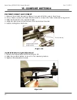
Page 21: ...tighten jam nut by turning clockwise 5 Repeat steps 1 4 on the other armrest Footrest Angle Adjustment 1 Fold the footrest upward for easy access to the angle adjustment bolt See figure 21 2 Turn the...

Page 22: ...to remove the bolts indicated in figure 22 3 Slide the footrest to the desired height 4 Align the bolt holes in the footrest and the footrest bracket 5 Install and tighten the bolts Joystick Bracket L...

Page 23: ...tick bracket to the armrest See figure 24 6 Place the joystick bracket on the opposite armrest align the two bolts with the two holes in the armrest and tighten to secure the bracket to the armrest 7...

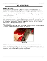
Page 24: ...described below and follow the instructions to safely operate your power chair DRIVING The Joystick On Off Switch Push the on off button to turn on the power to your Alant Sport See Figure 10 on page...

Page 25: ...ther forward or backward you push the joystick the faster your power chair will go To operate your power chair gently push the joystick in the direction in which you want to travel Gentle operation of...

Page 26: ...electrical components of your power chair The LED array does this by flashing on and off in a coded sequence The battery gauge and maximum speed profile indicator show the status of the control syste...

Page 27: ...ault If the fault does not clear go to the next step Switch off the control system Disconnect and reconnect all connectors on the wheelchair and the control system to make sure they are mated securely...

Page 28: ...hort circuit to a battery connection Contact your Golden Technologies representative 4 LEDs The right hand motor has a bad connection Check the connections to the right hand module 5 LEDs The right ha...

Page 29: ...ws the selected drive profile For example if drive profile 4 is selected then the fourth LED from the left will be illuminated Maximum Speed Profile Indicator Ripples Up and Down This indicated the co...

Page 30: ...WHEEL MODE To disengage the brakes and put your power chair in freewheel mode pull the levers forward towards the front of the power chair See Figure 26 To re engage the brakes and take your chair out...

Page 31: ...o your Alant Sport This device monitors the amount of current being drawn from the batteries when the chair is in use When the motors are heavily strained and too high a current draw is being placed o...

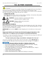
Page 32: ...tion IMPORTANT New batteries MUST be fully charged prior to the initial use of your power chair Charge new batteries for 12 hours even if the battery gauge already shows a full charge This is to condi...

Page 33: ...ck See Figures 29 and 30 4 Insert the plug at the other end of the charger power cord into a standard electrical wall outlet Power to the charger indicated by a red LED NOTE MAKE SURE THE STANDARD ELE...

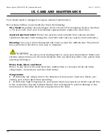
Page 34: ...clean the ABS shroud The shroud has a protective coat that is very easy to maintain Do not use free flowing water to clean your Alant Sport Water and extreme temperatures are the main elements that c...

Page 35: ...rity of the work for you If the door opens away from you 1 Use one hand to turn the door knob or to operate the push bar 2 Use your other hand to control the power chair by gently operating the joysti...

Page 36: ...e of the American Disabilities Act ADA many buildings are fitted with ramps that provide access for power chairs and for other mobility vehicles MANDATORY Please read and thoroughly understand Safety...

Page 37: ...U1 Colors Red Red Freewheel Mode Yes Yes Electronic Speed Control Yes Yes Electro Mechanical Brakes Yes Yes Charger Off Board Off Board Controller PG VR 2 50 Amp Remote PG VR 2 50 Amp Remote Length 4...

Page 38: ...st 26 5 30 0 30 5 34 0 Width x Depth 18 x 18 18 x 18 Color Gray Vinyl Coffee Sand Charcoal Gray Footrest Yes Yes Height adjustable Yes Yes Angle adjustable Yes Yes Warranty Frame Five Years Five Years...

Page 39: ...e period of thirteen months from the date of purchase in the event of defective materials or workmanship Golden Technologies will repair or replace at our option any of the following structural frame...

Page 40: ...maintenance or storage Commercial use or use other than normal Repairs and or modifications made to any part without the specific consent of Golden Technologies Exceeding the specified weight capacit...

Page 41: ..._________________________________________________ Address __________________________________________________________ City _____________________________________ State ______ Zip ____________ Serial Num...

Page 42: ...Alant Sport_GP205CC SS_Owner s Manual Rev C_102714 Fold Here First Golden Technologies 401 Bridge St Old Forge PA 18518 Fold Here Second Place Stamp Here...

Page 43: ...Alant Sport_GP205CC SS_Owner s Manual Rev C_102714...

Page 44: ...Sport_GP205CC SS_Owner s Manual Rev C_102714 Model GP205 Y O U R L I F E I N M O T I O N Alant Sport_OM_REVC_102714 401 Bridge Street Old Forge PA 18518 Tel 800 624 6374 Fax 800 628 5166 www goldentec...

Reviews: