background image

3. Plumbing

General Pool Equipment

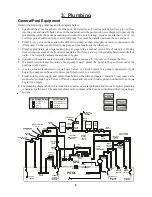
Refer to the following guidelines and the diagram below.
1. Spa should be at or above the level of the pool.  For raised spas: Provide a means for the spa to overflow

into the pool and install check valves in the spa return and the pool suction (see diagram) to prevent the

spa draining while the pool/spa suction and return valves are rotating.  If spa is not attached to pool:  An

overflow pipe of sufficient size to carry full pump flow must be installed between the spa and pool.

2. Plumb 3-way valve on the suction side of the filter pump, so that center port of valve is connected to the

filter pump.  Connect spa suction to one port, and pool suction to the other port.

3. Plumb appropriately sized spa makeup line (incorporating a manual valve and a check valve). During

pool circulation, some of the pool water needs to enter the spa to keep it chemically balanced and full of

water.  The ball valve adjusts the amount of bypass.

4. Systems with separate main drain and skimmer lines can use a 3-way valve to balance the flow.
5. If a pressure side cleaner requiring a boost pump is used,  plumb the  pump in the pool return (after the

pool/spa return valve).

6. A valve actuator (connected to Aqua Logic Valve3 or Valve4 output) or a pump (connected to Aqua

Logic Aux output can be used to direct pool return water to a waterfall.

7. Plumb solar system supply and return lines between the filter and heater.  Install a 3-way solar valve

(connected to Aqua Logic Valve3 or Valve4 output) and/or a solar booster pump (connected to an Aqua

Logic Aux output).

8.  The plumbing diagram below is intended to be used as a general guideline and is not a complete plumbing

schematic for the pool.  The diagram shows more equipment than can be controlled with an Aqua Logic

system.

8

FILTER

SOLAR BOOST

PUMP

SOLAR

VALVE

HEATER

HEAT
PUMP

HEATER
BYPASS

VALVE

(manual)

CELL

FLOW

SWITCH

CHECK

VALVE

POOL SWEEP
BOOST PUMP

WATER

FEATURE 

PUMP

POOL/SPA

RETURN 

VALVE

WATER

FEATURE

VALVE

SPA

SPA JET

PUMP

SPA

BLOWER

POOL/SPA SUCTION

VALVE

CHECK VALVE

POOL VACUUM

VALVE

MANUAL

VALVE

MANUAL

VALVE

MANUAL

VALVE

ENERGY

FILTER

TWO-WAY

VALVE

SKIM

POP-UP

SPILLOVER

POP-UP

OVERFLOW

POP-UP

RETURN

JET

IN-FLOOR
CLEANER

VALVE

WATER

FEATURE

PUMP

WATER

FEATURE

POP-UP

MAIN

DRAIN

ENERGY

SAVER

PRESSURE

CLEANER

NON-BOOST

PRESSURE

CLEANER

PRESSURE

CLEANER

SUCTION

CLEANER

SOLAR

TEMPERATURE

SENSOR

POOL

FILTER

PUMP

High Voltage Relays

Valve Outputs

Filter Pump
Lights
Aux 1

Aux 2

Pool/Spa Suction
Pool/Spa Return

Valve 3
Valve 4

TRANSFORMER

HIGH VOLTAGE

LIGHTS

LOW VOLTAGE

LIGHTS

FIBER OPTIC

LIGHT SOURCE

COLOR WHEEL

ISOLATED

WATER

FEATURE

PUMP

POOL/SPA

TEMPERATURE

SENSOR

CHECK

VALVE

(prevents draining

of raised spas)

CHECK

VALVE

(prevents draining

of raised spas)

Summary of Contents for Aqua Logic AQ-LOGIC-PS-4

Page 1: ...DLINE CONTROLS INC G www goldlinecontrols com 888 921 7665 Aqua Logic Aqua Logic Aqua Logic Aqua Logic Aqua Logic Automation and Chlorination Installation Manual for models AQ LOGIC PS 4 AQ LOGIC PS 8...

Page 2: ...nal must be connected to the grounding means provided in the electric supply service panel with a continuous copper wire equivalent in size to the circuit conductors supplying the equipment One bondin...

Page 3: ...less Remote Display Keypad 7 Optional Base Receiver 7 ValveActuators 7 3 Plumbing General Equipment 8 Turbo Cell 9 Flow Switch 9 4 Electrical Main Service 10 Wiring Grounding and Bonding 11 Circuit Br...

Page 4: ...rommainpaneltoAquaLogic Wire conduitforfilterpumpandotherhighvoltageloads Wireforbonding Miscellaneous Utilityelectricaloutletandweatherproofcover formountingonsideofAquaLogic Mountinghardware screws...

Page 5: ...red anexternalsubpanelcanbeused TheAquaLogiccontrolcircuitrequires120VACpower Autilityreceptacle notincluded canbemounted in the side of theAqua Logic box to provide 120VAC power if desired Installati...

Page 6: ...are using the chlorinator features on theAqua Logic Control If you are NOT using the chlorinator it is recommended that you follow all of the other chemistry recommendations be sides salt Refer to th...

Page 7: ...3 887 297 403 700 933 318 424 600 260 118 303 138 347 158 390 177 433 197 477 693 217 317 520 737 236 337 563 780 256 358 607 823 276 378 650 867 297 398 800 240 109 280 127 320 145 360 164 400 182 44...

Page 8: ...ngth x Width x Average Depth x 1000 POUNDS and Kg OF STABILIZER CYANURIC ACID NEEDED FOR 80 PPM Gallons and Liters of Pool Spa water Current Stabilizer Level ppm 0 ppm 20 ppm 60 ppm 30 ppm 40 ppm 50 p...

Page 9: ...nsertsensoruntilO ringcollarsitsflushonthehole 3 Position hose clamp over the sensor and gently tighten until O ring makes an adequate seal Do not overtighten 4 For maximum temperature accuracy cover...

Page 10: ...ss remote display keypad Follow the steps below 1 Remove the display keypad baseplate from the cover by lifting up on the cover at the lower end of the keypad See diagram above 2 Screw the baseplate i...

Page 11: ...Aqua Logic Aux output can be used to direct pool return water to a waterfall 7 Plumb solar system supply and return lines between the filter and heater Install a 3 way solar valve connected to Aqua L...

Page 12: ...ptors providedbyinstaller Flow Switch TheflowswitchmustbeplumbedinthesamesectionofplumbingastheTurboCell Theflowswitchisa safety device that ensures that water is flowing through the cell before theAq...

Page 13: ...ircuit Breaker Subpanel TheAqua Logic circuit breaker subpanel is rated for 100Aservice Run properly rated conductors L1 L2 N and ground from the primary house electrical panel to the main power conne...

Page 14: ...may be required to be connected to ground fault circuit breakers check local and NEC CEC codes General Purpose Outlet If desired a duplex receptacle with weatherproof cover supplied by installer may b...

Page 15: ...ure to follow the wiring diagram belowAND to configure the control logic according to the instructions on page 19 Lights Aground fault circuit breaker must be used to supply power for high voltage poo...

Page 16: ...reisonapoolthathasbothagasheater forrapidheatingofthespa andaheat pump for economical heating of the pool IMPORTANT If you chose to use the Heater2 control output then you will not be able to use the...

Page 17: ...o guidance is given use 105 C rated wire 3 Set any ON OFF switch on the heater to ON 4 Set the thermostat s on the heater to the maximum hottest setting Laars Heaters most models except LX 1 Turn powe...

Page 18: ...erAquaLogicrequests whenAquaLogic Heater LEDisilluminated Pentair Purex MiniMax 1 Turn power off to heater 2 Removefactoryinstalledjumperfromthe ExtSwitch connector 3 Wire theAqua Logic to the Ext Swi...

Page 19: ...mistake change the mode to POOL or SPA which then disables the remote control by theAqua Logic To prevent this Remove the heater touch pad connector P5 which will disable the touchpad STA RITE Heater...

Page 20: ...it can connect to a maximum of 3 remote wired display keypads One remote wireddisplay keypadisincludedwiththeAquaLogic additionalwireddisplay keypadsmustbeordered separately Use four conductor cable t...

Page 21: ...receiverintothe wireless connectoronthemainPCB intheAquaLogiccontrolunit Flow Switch Only applicable if the chlorinator function is enabled The flow switch cable plugs into theAqua Logic ControlCenter...

Page 22: ...bled Toggle between Enabled default and Disabled Chlorinator Move to previous next configuration menu item Chlorinator If the chlorinator is enabled default then the cell and flow switch must also be...

Page 23: ...r separate pool and spa settings Depending on the position of the pool spa suction valve the proper temperature setting will be used Heater Name The Aqua Logic allows you to assign any one of a number...

Page 24: ...ng on the position of the pool spa suction valve the proper temperature setting will be used Solar Extend If Enabled the filter extend logic keeps the filter pump running beyond the normal turn off ti...

Page 25: ...hts Name Pool Light Push to access Lights options Rotates between Manual On Off default Countdown Timer and Timeclock Rotates between all available names Move to previous next configuration menu item...

Page 26: ...Aqua Logic main unit and each remote display keypad so that the Aux pushbutton can be labeled the same as the name that you have assigned At this time it is also a good idea to make sure that the rela...

Page 27: ...Disabled Toggle between Enabled and Disabled default Valve3 Interlock Toggle between Enabled and Disabled default Valve3 Freeze Move to next menu item Move to next menu item for all functions except s...

Page 28: ...tion menu item Toggle between 7 day default and Weekend Weekday time options This selection affects ALL of the timeclock logic in the Aqua Logic If 7 day is selected each timeclock will have one set o...

Page 29: ...EDisilluminated godirectlytostep2 ifnot thencheckthefollowing Theheaterisenabled ConfigurationMenu HeaterConfig The heater temperature setting is at least 2 F greater than the water temperature Settin...

Page 30: ...out of Service mode FCC Statement Compliance Statement Part 15 19 This device complies with Part 15 of the FCC Rules Operation is subject to the following two conditions 1 This device may not cause h...

Page 31: ...e Aqua Trol or Aqua Logic electronics unit will be the sole determinant of the date of the initial system installation If a product is defective in workmanship or materials and is removed and returned...

Page 32: ...F spa heater2 temp off 65 F 104 F pool heater2 temp off 65 F 104 F spa solar temp off 65 F 104 F pool solar temp off 65 F 104 F superchlorinate on off spa chlorinator setting 0 100 pool chlorinator se...

Reviews: