background image

Introduction

Before You Begin

What’s Included

Before attempting to install the Pro Logic system, check that the following components have been included in the

package:

Pro Logic Electronics Unit

  (3) Temperature sensors with 15 ft. (5m) cable, hose clamp

What’s NOT Included

Some of the additional items that you may need to complete an installation include:

Circuit breakers

None are included with control—see page 10 and inside of door for suitable breakers

Wire

4-conductor cable (electronics unit to remote display/keypad)

Wire/conduit for 100A service from main panel to Pro Logic

Wire/conduit for filter pump and other high voltage loads

Wire for bonding

Miscellaneous

Utility electrical outlet and weatherproof cover (for mounting on side of Pro Logic)

Mounting hardware (screws, etc.) for mounting Pro Logic and remote display/keypad

Valves (use standard Hayward, Pentair/Compool, or Jandy valves)

Additional valve actuators

Accessory Products - Order Separately

T-CELL-3

Chlorinator Cell (for pools up to 15k gallons)

T-CELL-9

Chlorinator Cell (for pools up to 25k gallons)

T-CELL-15

Chlorinator Cell (for pools up to 40k gallons)

P-KIT

Chlorination plumbing kit containing flow switch and cell unions

AQL-CHEM

ORP & pH sense kit

AQL-CHEM2(-240)

pH dispense kit

AQL-WW-P-4

Wired Wall Mount Remote Display

AQL-SS-6B-x (x=W/B)

Wired Spa Side 6 Function Remote Control, 150ft cable, specify color (white or black)

AQL2-POD

Handheld Wireless Waterproof Remote with Charging Station (AQL2-BASE-RF required)

AQL2-Tx-RF-P-4

Wireless Table Top remote (AQL2-BASE-RF required)

AQL2-SS-RF

Wireless Spa Side Remote Control (AQ2L-BASE-RF required)

AQL2-BASE-RF

Base Receiver

AQL-DIM

Light Dimmer Relay

GVA-24

Valve Actuator

V&A-xx

Valve & Actuator (xx=1P (1.5” pos. seal), -2P (2” pos. seal)

NOTE: Before installing this product as part of a saline water purification system in a pool or spa using natural stone for

coping or for immediately adjacent patios/decking, a qualified stone installation specialist should be consulted regard-

ing the appropriate type, installation, sealant (if any) and maintenance of stone used around a saline pool with electronic

chlorine generator in your particular location and circumstances.

NOTE: The use of dry acid (sodium bisulfate) to adjust pool pH is discouraged especially in arid regions where pool

water is subject to excessive evaporation and is not commonly diluted with fresh water. Dry acid can cause a buildup

of by-products that can damage your chlorinator cell.

Installation Steps

Details on each installation step are presented on the following pages:

1.  Prepare the pool water  (page 2)

General Water  Chemistry

Salt

2.  Mounting the equipment (page 5)

Pro Logic main unit

Temperature sensors

Remote display/keypad (optional)

Valve actuators (if applicable)

1

30

6.  System Startup and Checkout

Before Startup

Before starting the Pro Logic for the first time, be sure that the following items have been completed:

1. Pool/spa chemicals are within the recommended levels according to the chart on page 2.

2. Pool/spa salt level is between 2700 – 3400 PPM.

3. Properly rated circuit breakers are installed in the Pro Logic subpanel.

4. All wiring is performed according to NEC and local codes.

5. The Pro Logic is properly grounded and bonded.

6. The Pro Logic is properly configured to control all desired functions.

Program Automatic Operation

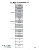
Refer to the programming flow chart on the back cover of this manual for a listing of the available menus and the items

included in each menu.

Settings Menu

Heater and/or solar thermostat settings

Chlorinator settings

Day and Time

Timers Menu

Timeclock and/or Countdown timer settings

Heater Checkout

Follow these instructions to verify that the Pro Logic is properly controlling the heater.

1. Check that the Pro Logic is calling for the heater to turn on as indicated by the “Heater” LED being illuminated. If the

“Heater” LED is illuminated, go directly to step 2; if not, then check the following:

The heater is enabled (Configuration Menu/Heater Config.).

The heater temperature setting is at least 2ºF greater than the water temperature (Settings Menu / Pool Heater

& Spa Heater).

The filter pump is running.

If the pool has solar heat and the solar priority feature is enabled (Configuration Menu/Solar Config) then solar

must be off in order for the heater to fire. The easiest way to force solar off is to go to the Settings Menu / Pool

Solar & Spa Solar and temporarily lower the temperature settings below the current water temperature.

2. Check that the heater is running. If not, then check:

Power is supplied to the heater.

The Pro Logic control output is properly connected to the heater control (see ”Heater Control” wiring, page

14).

Some heaters also have internal switches or jumpers that have to be set correctly for remote control opera-

tion—refer to the heater manual and also “Heater Control” (page 13).

Heater is turned on (“Kill Switch” is in the “ON” position).

If a heater bypass valve is installed, check that water is flowing through the heater.

The heater temperature setting is set as high as possible (usually 104ºF/40ºC).  Also note that some heat

pumps actually have be set to the lowest possible temperature.

3. Once the heater is running, you can verify the “heater cooldown” feature (optional - see Configuration Menu/Heater

Config.) is operating properly:

Press the “Filter” button once (for 2 speed pumps, this may require 2 pushes of the “Filter” button).

The heater should turn off (“Heater” LED off) and the “Filter” LED will flash to indicated heater cooldown is

active.

3.  Plumbing  (page 8)

General Pool Equipment

Turbo Cell

Flow Switch

Summary of Contents for Pro LOGIC PL-P-4

Page 1: ...www goldlinecontrols com Automation and Chlorination Installation Manual for model PL P 4 LD C G LINE ON TROLS ...

Page 2: ...nal must be connected to the grounding means provided in the electric supply service panel with a continuous copper wire equivalent in size to the circuit conductors supplying the equipment One bonding lug for US models two for Canadian models is provided on the external surface To reduce the risk of electric shock connect the local common bonding grid in the area of the swimming pool spa or hot t...

Page 3: ... Remote Controls 6 Optional Base Station 7 Optional ValveActuators 7 3 Plumbing Pool Spa Configuration 8 TurboCell 9 Flow Switch 9 4 Electrical Main Service 10 Wiring Grounding and Bonding 10 Circuit Breaker Installation and Wiring 10 General Purpose Outlet 11 Pro Logic Control Power 11 High Voltage Pool Equipment 11 Low Voltage Wiring 13 5 Configuration Configuration Menu 20 6 System Startup Befo...

Page 4: ...lay AQL SS 6B x x W B Wired Spa Side 6 Function Remote Control 150ft cable specify color white or black AQL2 POD HandheldWireless Waterproof Remote with Charging Station AQL2 BASE RF required AQL2 Tx RF P 4 Wireless Table Top remote AQL2 BASE RF required AQL2 SS RF Wireless Spa Side Remote Control AQ2L BASE RF required AQL2 BASE RF Base Receiver AQL DIM LightDimmerRelay GV A 24 ValveActuator V A x...

Page 5: ...onfiguration page 20 6 System Startup and checkout page30 1 Preparing Pool Spa Water General Water Chemistry Salt is required only if you are using the chlorinator features on the Pro Logic Control If you are NOT using the chlorinator it is recommended that you follow all of the other chemistry recommendations besides salt Refer to the descriptionoftheProLogicconfigurationmenuforinformationonenabl...

Page 6: ...2 23 30 45 60 32 80 36 90 41 100 45 110 160 50 73 120 170 55 77 130 180 59 81 140 190 64 86 150 200 68 90 93 42 107 48 120 55 133 61 147 213 67 98 160 227 73 104 173 240 79 110 187 253 85 117 200 267 91 123 2200 3000 2800 2400 3200 Ideal Ideal Ideal Ideal Ideal Ideal Ideal Ideal Ideal Ideal Ideal Ideal Ideal Ideal Ideal 2600 3400 OK OK OK OK OK OK OK OK OK OK OK OK OK OK OK OK OK POUNDS and Kg OF ...

Page 7: ...th x Average Depth x 893 Length x Width x Average Depth x 1000 POUNDS and Kg OF STABILIZER CYANURIC ACID NEEDED FOR 80 PPM Gallons and Liters of Pool Spa water Current Stabilizer Level ppm 0 ppm 20 ppm 60 ppm 30 ppm 40 ppm 50 ppm 70 ppm 80 ppm 10 ppm 12 000 45000 8 000 30000 14 000 52500 10 000 37500 16 000 60000 18 000 67500 20 000 75000 22 000 82500 32 000 120000 24 000 90000 34 000 127500 26 00...

Page 8: ...or and gently tighten until O ring makes an adequate seal Do not overtighten 4 For maximum temperature accuracy cover the sensor and 3 6cm of pipe on either side with insulation and whitepaint Air Sensor Mount the air sensor outdoors IMPORTANT Mount the air sensor out of direct sunlight Solar Sensor For solar applications mount the sensor near the solar collector array so that it is exposed to the...

Page 9: ...he unit The display keypad is designed to mount onto a standard electrical utility box same box as a single light switch ideal for new construction or can be mounted directly onto any wall surface When selecting a location note thatthewiretotheProLogicmainunitmustbelessthan500 long Refertotheremote sinstallationinstructionsaswell as the steps below 1 Remove display keypad baseplate from the cover ...

Page 10: ...able battery operated remote control designed to be used in a weather protected area rainshouldneverhittheunit Thisremotecomeswithawallmountedpowersupplyforrechargingthebuilt inbatteries AQL2 SS RF AQL2 POD TheAQL2 SS RF andAQL2 POD are waterproof portable remote controls that are designed to be used in and around the pool spa area These units float and can be left in the water for easy access Opt...

Page 11: ...dthe systemisinthe poolonly operatingmode 6 The plumbing diagram above is intended to be used as a general guideline and is not a complete plumbing schematicforthepool 7 Theairsensormustbeinstalledifthefreezeprotectionfeatureisenabledforthefilter valvesorauxoutputsor ifthechlorinatorisenabled 8 FILTER SOLAR BOOST PUMP SOLAR VALVE HEATER HEATER BYPASS VALVE manual CELL FLOW SWITCH CHECK VALVE POOL ...

Page 12: ...h1 plumbinguseadaptors providedbyinstaller Flow Switch supplied with P KIT TheflowswitchmustbeplumbedinthesamesectionofplumbingastheTurboCell Theflowswitchisasafetydevice thatensuresthatwaterisflowingthroughthecellbeforetheProLogicstartstogeneratechlorine Failuretoproperly installtheflowswitchcanresultinexplosivegasesaccumulatinginthepoolplumbingsystem IMPORTANT There must be at least a 12 30cm st...

Page 13: ... equipment that is connected to the Pro Logic control relays or circuit breakers The Pro Logic should also be connected to the pool bonding system by an 8AWG 6AWG for Canada wire Alug for bonding 2 for Canada is provided on the outside bottom of the Pro Logic enclosure Circuit Breaker Installation and Wiring Circuitbreakersaretobesuppliedbytheinstaller Refertothecircuitbreakerchartonthefollowingpa...

Page 14: ...s and the chlorinator This power should be connected to one of the circuit breakers WARNING 120VAC only permanent damage if connected to 240V High Voltage 120 240V Pool Equipment All Pro Logic relays are double pole they make break both legs of 240V circuits and are rated at 3HP 30A at 240V 1 HP 30A at 120V Refer to the diagram below for typical relay wiring 11 Factory Prewired Field Wired 120 2VA...

Page 15: ...rproperinputwiringtotheVSC Wiringfromthe220VbreakermustconnectthroughtheProLogic sFilter relay The Filter relay is used to supply input power to theVSC pump control The relay will be on when the filter pumpoutputison Whenthefilterpumpoutputisoff therelaywillbeoff Notethatwhenthefilterpumprelayisoff power off to the VSC the Pro Logic will not display errors or diagnostics for the pump The filter pu...

Page 16: ...pumpswith 24V control circuits Refer to the diagram below for a generic connection The manuals supplied with most heaters alsoincludespecificwiringinstructionsforconnectingtheheatertoanexternalcontrol usuallyidentifiedas 2 wire remote control For millivolt or line voltage heaters contact Goldline Tech support 908 355 7995 Refer to the diagramsandtheinformationonthefollowingpagesformoredetailsonthe...

Page 17: ...dthediagrambelow 1 Turn off power to heater 2 Wire Pro Logic to terminals 1 2 see diagram 3 Leave jumper attached to terminals 4 5 4 Move BYPASS dipswitch on heater circuit board to ON position up 5 Turn heater power back on 6 Switch heater to either Pool or Spa it doesn t make any difference which is selected the Pro Logic will take control 7 Heater display should be bO for bypass On 8 Heaterwill...

Page 18: ...r 1 Turn power off to heater 2 Push the mode button to spa mode 3 Set the temperature to the maximum 4 Push the mode button to OFF 5 Lastly plug the prewired connector in the P7 position on the board IMPORTANT The heater will display OFF when it is being remotely controlled by the Pro Logic Some homeowners see the OFF display and thinking this is a mistake change the mode to POOL or SPA which then...

Page 19: ...onnect screw terminals 1 to 1 2 to 2 etc Usefourconductorcable typicallyphonecable forcommunicationsconnectionbetweentheVSCandtheProLogic The maximum wiring distance is 500 feet 160 meters Note that the terminals on both the VSC interface board and theProLogicmainboardarenumbered Theterminalconnectionsshouldbematchedbetweenbothterminalblocks connect 1 to 1 2 to 2 etc The communications cable shoul...

Page 20: ...ation AIR SENSOR SOLAR SPA SENSOR POOL SPA SENSOR RemoteDisplay Keypad The Pro Logic main unit can connect to a maximum of 3 remote wired display keypads ordered separately Use four conductor cable typically phone cable to connect the wired remote display keypad with the Pro Logic ControlCenterasshownbelow Themaximumwiringdistanceis500ft 160m Notethattheterminalsonboththe ProLogicmainunitandthewir...

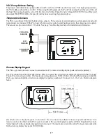
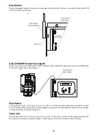
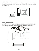
Page 21: ...inthe Pro Logic control unit as shown below Connector for AQL CHEM Flow Switch Only applicable if the chlorinator function is enabled The flow switch cable plugs into the Pro Logic ControlCenteratthepositionshowninthediagramonpage10 Ensurethattheconnectorcatch snaps in order to provide a reliable connection Turbo Cell Only applicable if the chlorinator function is enabled The Turbo Cell should be ...

Page 22: ...lorinatorswhenadditionalsanitizingcapacityisrequired A4 wire connection is used to communicate to theAqua Rite and can be wired up to 500 apart Any outdoor rated 4 conductor cable can be used Refer to the wiring diagrams below for proper wiring connection to theAqua Rite NOTE Theremustbeonly1 primary unit AllotherAquaRiteunitsmustbeconfiguredas secondary 19 Pro Logic Aqua Rite Primary Aqua Rite Se...

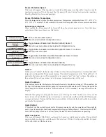
Page 23: ...to next menu item Chlorinator Enabled Display Salt Chlor Config to view change Toggle between Display Salt default and Minerals Toggle between Chlorinator Enabled and Disabled default Move to previous next configuration menu Move to next configuration menu Push to access Chlorinator option Cell Type T CELL 15 Chlorinator Enabled Display Salt Chlor Config to view change Chlorinator Requires the use...

Page 24: ...Spa is selected then the pool spa suction and return valve actuators should be connected to the Pro Logic Pressing the POOL SPA button on the display keypad will allow the homeowner to alternate between pool and spa operation For more information on Pool and Spa refer to the Plumbing section on pages 8 Spa CountDn This menu will appear only if Pool Spa Setup is set to Pool and Spa This setting is ...

Page 25: ...ed and 1 speed Filter is not selected Filter Pump For 2 speed pumps When a 2 speed pump is configured one of theAUX relays must also be configured to control the low speed motor winding on the pump Refer to the appropriate sections in the Installation manual for specific information regarding the control logic for 2 speed and variable speed pump operation For the Hayward Tristar variable speed pum...

Page 26: ... the heater relay will turn on when the water temperature is less than the desired temperature setting and the filter pump is running The desired temperature is in the Settings Menu If applicable the homeowner will be prompted to enter separate pool and spa settings Depending on the position of the pool spa suction valve the proper temperature setting will be used Heater Cooldown This feature ensu...

Page 27: ...ired temperature is in the Settings Menu If applicable the homeowner will be prompted to enter separate pool and spa desired temperature settings Depending on the position of the pool spa suction valve the proper temperature setting will be used Solar Extend If Enabled the filter extend logic keeps the filter pump running beyond the normal turn off time if solar heat is still available When solar ...

Page 28: ...down Timer the lights relay will turn on when the LIGHTS button is pressed The lights relay will turn off automatically after a programmed time see Timers Menu in Operation Manual The LIGHTS button can also be used to turn the output off Low Speed of a 2 speed Filter Pump the Pro Logic will turn on the lights relay whenever the low speed operation of the filter pump is required It is very importan...

Page 29: ...1 Freeze default Move to next menu item Move to previous next configuration menu for manual on off countdown timer and timeclock functions Move to next menu item Rotates between Manual On Off default Countdown Timer Low Speed Filter Timeclock Solar and Super Chlorinate for all functions except dimmer relay solar super chlorinate and low speed f super chlorinate and low speed or all functions excep...

Page 30: ...he AUX output during freeze see the Filter Pump Config menu to enable freeze protection for the main circulation system Valve3 Disabled Freeze Toggle between Enabled and Disabled default Valve3 Freeze Move to previous next configuration menu for all functions except super chlorinate Valve3 Config to view change Valve3 Function Solar Push to access Valve3 options Rotates between k Timecloc default ...

Page 31: ...ion menu Move to previous next menu item or next configuration menu Move to next menu item if AQL SS 6B is connected Select 6B Spa This menu only appears if more than oneAQL SS 6B is detected at power up Select which of the available remote controls A B or C is to be configured 6BA Button 1 This menu allows the user to map each button of the AQL SS 6B to one of the standard Pro Logic functions The...

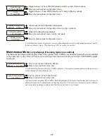
Page 32: ...tion is NOT reversible be careful Maintenance Menu only displays if Sensing System is enabled TheMaintenanceMenuwillbedisplayedonlyiftheoptionalAQL CHEMisusedandtheSensingSystemisenabled in the Chemistry Config Wizard This menu is used to perform functions relating to theAQL CHEM ORPand pH sensingkit pH Calibration Wizard to enter Push to access pH Calibration Wizard Move to previous next menu ite...

Page 33: ...erthanthewatertemperature SettingsMenu PoolHeater Spa Heater Thefilterpumpisrunning Ifthepoolhassolarheatandthesolarpriorityfeatureisenabled ConfigurationMenu SolarConfig thensolar mustbeoffinorderfortheheatertofire TheeasiestwaytoforcesolaroffistogototheSettingsMenu Pool Solar Spa Solar and temporarily lower the temperature settings below the current water temperature 2 Check that the heater is r...

Page 34: ...servicemode pushtheSERVICEbuttononceonthemainunitkeypad Thiswillinitiallyturnalloutputsoffand thenallowyoutoturnoutputson offmanuallyatthemaindisplay only In servicemode thebuttonsontheoptional remotedisplay keypad andtheoptionalspasideremotewillturnoutputsoff butwillnotturnanyoutputon Heater control outputs and solar control outputs are prevented from turning on if the water temperature exceeds 1...

Page 35: ...rocess of installation 2 Damageresultingfromimproperinstallationincludinginstallationonpoolslargerthantheproductrating 3 Problemsresultingfromfailuretoinstall operateormaintaintheproduct s inaccordancewiththerecommen dationscontainedintheownersmanual s 4 Problemsresultingfromfailuretomaintainpoolwaterchemistryinaccordancewiththerecommendationsinthe ownersmanual s 5 Problemsresultingfromtampering a...

Page 36: ...igh low speed day and time backlit display light beeper teach wireless remote wireless channel maintenance menu pH calibration wizard clean probe wizard timers menu pool filter pump1 or hi speed pool filter pump2 or lo speed spa lights aux1 aux2 valve3 superchlorinate diagnostic menu chlorinator diagnostics instant salt pH ORP levels flow switch cell temperature sensor water sensor air sensor sola...

Reviews: