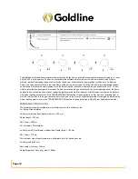
background image

Page 10


5. 

Gas connection 


Install in accordance with relevant gas standards and

/

or codes of practice applicable

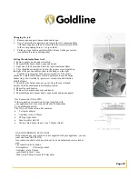
Connect the elbow fitting to the appliance gas 

manifold connection

and check that seal

s between the elbow and manifold connection are in place and in good condition.


 For Natural gas : connect the natural gas appliance regulator (pictured opposite) with integral test point using approved gas thread tape or 
compound to the elbow fitting. 


    For Universal LPG : connect the Test point adapter (pictured below) with integral test point using approved gas thread tape or compound to 
the elbow fitting. 


LPG testpoint


Natuaral Gas Reguator


i
n
l
e
t
 
c

Ensure the supply connection point

test point and natural gas regulator adjustment screw 

(

for Natural gas installation

are acces-

sible for testing and

/

or adjustment with the hotplate in the installed position

Where a flexible hose assembly is used

ensure it is 

approved to AS

/

NZS 1869

Class B or D with max

length of 1

.

2m

Any hose assembly used must be restrained from accidental 

contact with the flue outlet of an under bench oven

This hose assembly shall be suitable for connection to a fixed consumer 

piping outlet located as follows

Hotplates at a point 800 mm to 850 mm above the floor and in the region outside the width of the 

appliance to a distance of 250 mm


Note: 

If clearance between side and rear walls and periphery of the burner is less than 250mm, the walls must be protected with a 

non

-

combustible 

The protection must 

 minimum distance of 450mm above the burner. Horizontal surfaces less 

than 650mm vertically above the hotplate must also be protected.


Summary of Contents for SAB Series

Page 1: ...GOLDLINE GAS COOKTOP SAB SERIES USER MANUAL ...

Page 2: ...GL SAB704GL SAB5GL Content Safety instructions 2 Product description 4 Specifications Table 6 Installation 8 Start Using your cooktop 13 Maintenance and troubleshooting 15 Servicing 19 NOTE This User Instruction Manual contains important information including safety installation points which will enable you to get the most out of your appliance ...

Page 3: ...ce safely should not use this device without supervision or instruction by a responsible person This appliance should be used only for normal domestic cooking and frying of food The appliance must not be used as a work surface or as a storage surface Additions or modifications to the appliance are not permitted Do not place or store flammable liquids highly inflammable materials or fusible objects...

Page 4: ...any does not accept any responsibility for loss or damage of the Goldline product prior to it being received by the Company or its service agent Please dispose or recycle any packaging material How to avoid damage to the appliance The glass toughened can be damaged by objects falling onto it The edge of the glass ceramic can be damaged by being knocked by the cookware Cookware made of cast iron ca...

Page 5: ...K AUX SEMI RAPID WOK CONTROL KNOBS Layout for different models will vary Please see SPEC table for burner details of each model Accessory Name Picture for reference only physical unit maybe different Quantity User Manual 1 Installation clip 3 Screws ST4 2x18 3 Adhesive sealing tape 3 Natural gas regulator 1 Test point adapter 1 ...

Page 6: ...Page 6 ...

Page 7: ...re isn t a specific clearance requirement un der the Building Code of Australia Like all appliances though these need to be installed according to statutory requirements and so that the installation meets the manufacturer s specifications The Standard also states that the horizontal clearance from a hotplate or burner to a vertical combus tible material like an acrylic splashback for example shoul...

Page 8: ...r flame for correct operation If burner is placed correctly it will not rotate on its supports The DCC Wok burner diagrams below does not fit over the igniter or thermocouple but must be placed on its supports 2 Place burner box Apply the adhesive sealing tape to the underside lip of the burner box Shown at G opposite Place burner box into cutout hole and fit clamping brackets to clamp the hotplat...

Page 9: ...supplied must not touch against any hot surfaces and must be placed so that its temperature does not exceed 75 at any point along its length After having installed the hotplate the GPO must always be in an accessible position Wiring diagram for SAB4GL SAB4GLH SAB704GL Wiring diagram for SAB5GL Wiring diagram for SAB301GL SAB302GL SAB402GL SAB2GL Wiring diragram for SAB3GL SAB603GL ...

Page 10: ...gas regulator adjustment screw for Natural gas installation are acces sible for testing and or adjustment with the hotplate in the installed position Where a flexible hose assembly is used ensure it is approved to AS NZS 1869 Class B or D with max length of 1 2m Any hose assembly used must be restrained from accidental contact with the flue outlet of an under bench oven This hose assembly shall be...

Page 11: ...pplied in separate bag on a surface adjacent to the hotplate for example the inside of the cupboard door so it is clearly visible for any service technician SETTING THE GAS PRESSURE Fit a manometer with a 6 mm rubber hose to the test point on the regulator for natural gas For all the mod els light all burners on and adjust test point pressure to 1 00 kPa Turn burners off and on again and recheck t...

Page 12: ...ame safeguard has not heated up enough so repeat the ignition procedure after waiting 1 minute for gas to disperse If problems with burner lighting persist refer to the TROUBLESHOOTING section of these instructions If power is not available light a match or similar then turn the gas control knob for the burner to be lit to the High Flame setting Once again if problems with burner lighting persist ...

Page 13: ...est efficiency and to ensureutensil handle does not over heat place the utensil centrally on the burner and adjust the flame height so all the flame remains under the utensin NOTE Enclosure may be be circular or sqaure ...

Page 14: ...shed with a sponge and soapy water or with non abrasive products Rinse with clean water Dry with a clean dry cloth BURNERS Remove trivets from hob Ensure that burners are cool Remove the burners enameled cape and aluminum burner crown F Wash down with warm soapy water and rinse with clean water Dry with a clean dry cloth Use a cotton bud toothbrush or some other similar item to clean out any incru...

Page 15: ...s to clamp the hotplate to the bench Electrical connection Install a 10 amp general purpose outlet GPO in accordance with relevant electrical standards and or codes of practice applicable The power supply cord supplied must not touch against any hot surfaces and must be placed so that its temperature does not exceed 75 degree at any point along its length After having installed the hotplate the GP...

Page 16: ... ring if not turn the by pass screw clockwise until satisfied with the flame 5 Check that the burner does not go out when the tap is turned quickly from the maximum to minimum position 6 Repeat for each burner 7 Remove the burner heads caps and knobs 8 Reassemble panels burner heads caps knobs and pan supports Gas Conversion NG to LPG If the required gas conversion kit is not supplied with your ap...

Page 17: ...ice representative Servicing beyond the remedies listed shall only be undertaken by an authorized service representative FAULT CAUSES REMEDY Burner will not light 1 Air in gas line 2 Blockage in line 3 Ignition not sparking 4 Flame failure device faulty 5 Check the battery applicable to DC version 1 Purge gas line Trace back and clear 3 Check lead and electrode 4 Replace thermocouple and test 5 Re...

Page 18: ... Remove glass hob and control knobs To remove gas cocks Unscrew the locking nut between cock and burner Remove screws the cock can now be removed from the manifold If access to the barrel is required remove two screws which retain spindle to body If lu bricating the mechanism use Regosine Moly LM or other approved grease To replace electrode Remove screw from the clamp holding the electrode and th...

Page 19: ... to perform to the Company s specifications as a result of some defect in materials components or workman ship Defect then the Company will at its option repair the Goldline product or supply a replacement Gold line product free of charge A replacement Goldline product may differ from the original product purchased by the Consumer 1 7 This warranty will not apply to any Goldline product 1 7 1 Inst...

Page 20: ...ctive through no fault of the Owner and is otherwise undamaged the Company will repair or replace the Goldline product in accordance with this warranty DO NOT SEND IN THIS WARRANTY Fill out the following details and file with your purchase invoice RET AIN FILE WITH YOUR RECEIPT Your Purchase Receipt Invoice is proof of date of purchase If you are unable to establish the date of pur chase or if the...

Reviews: