background image

17

HOW TO USE THE MANUAL MODE

Note: If there is a sheet of clear plastic on the face of

the console, remove the plastic.

1. Press any button on the console or begin ped-

aling to turn on the console.

When you turn on the console, the displays and

the target pacer coach will light. A tone will then

sound and the console will be ready for use.

2. Select the manual mode.

When you turn on the console, the manual mode

will be selected. If you have selected a workout,

reselect the manual mode by pressing any of the

Quick Workouts buttons repeatedly until a track

appears in the left display.

3. Begin pedaling and change the resistance of

the pedals as desired.

As you pedal, change

the resistance of the

pedals by pressing the

Quick Resistance but-

tons. Note: After you

press the buttons, it

will take a moment for the pedals to reach the

selected resistance level.

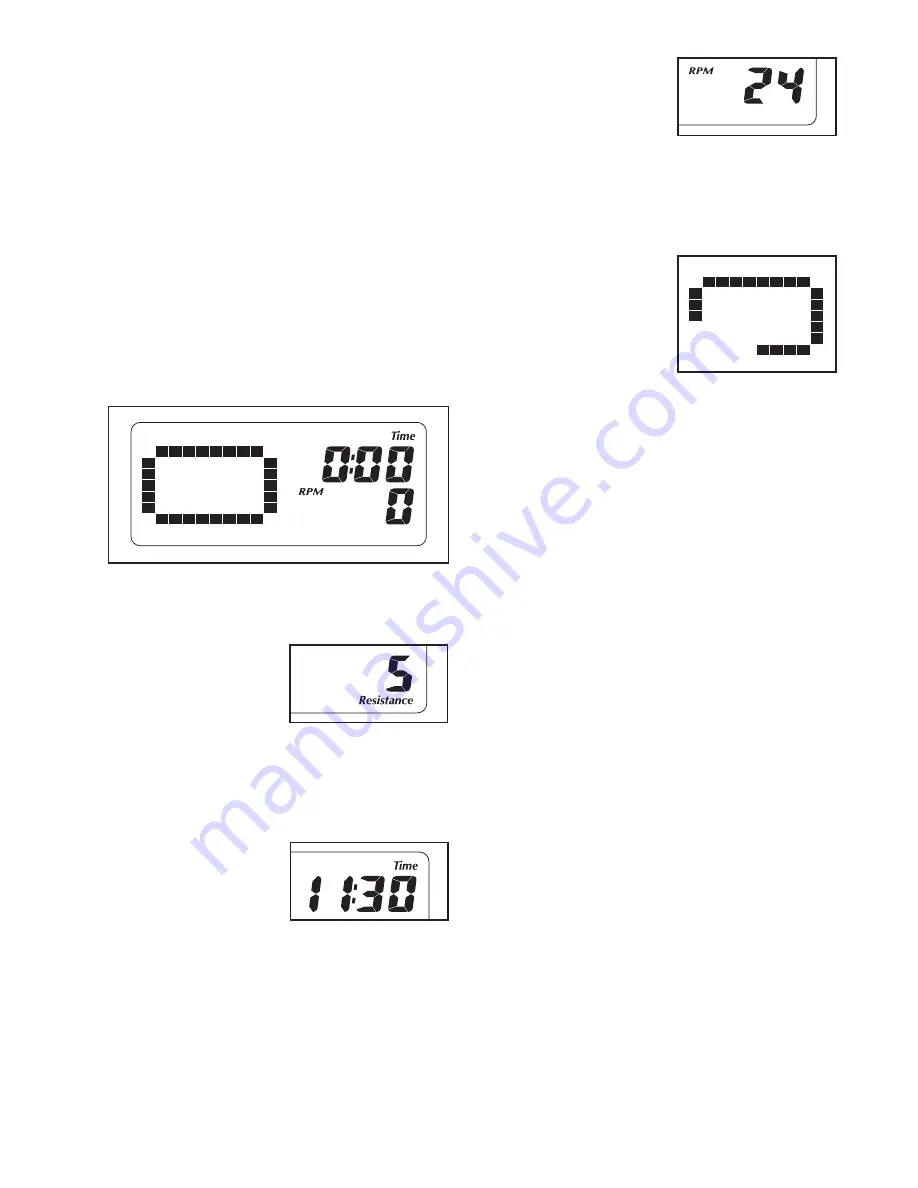
4. Follow your progress with the displays.

The upper right

display can show the

elapsed time, the dis-

tance (total revolutions)

you have pedaled, the

approximate number of

calories you have burned, and the approximate

number of grams of carbs you have burned. The

display will change modes every few seconds.

The lower right

display can show your

pedaling pace in revo-

lutions per minute

(rpm) and the resis-

tance level of the ped-

als. The display will change modes every few sec-

onds. The display will also show your heart rate

when you use the handgrip pulse sensor (see step

5 on page 18).

The left display will

show a track repre-

senting 640 revolu-

tions. As you exercise,

indicators will appear in

succession around the

track until the entire

track appears. The

track will then disappear and the indicators will

again begin to appear in succession.

To change the display mode, press the Display but-

ton repeatedly until the desired exercise information

appears in the upper or lower right display. After

several seconds, the display will change modes

automatically as before.

To view the trip distance, press the Odometer but-

ton. The information will appear in the display for a

few seconds. To reset the trip distance, hold down

the Odometer button for a few seconds. To view

the total distance pedaled since the elliptical exer-

ciser was purchased, press the Odometer button a

second time. (Note: The number on the right side

of the display multiplied by the number on the left

side equals the trip distance or the total distance.)

To adjust the volume level of the console, first

press and hold down the Display button until the

display becomes blank. When you release the

Display button, the volume level will then appear in

the display. Press the increase and decrease but-

tons located above the Heart Rate buttons to

select a volume level. Then, press the Display but-

ton.

Summary of Contents for GGEL66008.0

Page 1: ...AL QUESTIONS As a manufacturer we are commit ted to providing complete customer satisfaction If you have questions or if parts are damaged or missing DO NOT CONTACT THE STORE please contact Customer C...

Page 2: ...MITED WARRANTY Back Cover 2 WARNING DECAL PLACEMENT The drawing here shows the location s of the warning decal s If a decal is missing or illegible see the front cover of this manual and request a fre...

Page 3: ...m of clearance in the front and rear of your ellipti cal exerciser and 2 ft 0 6 m on each side 5 Inspect and properly tighten all parts regu larly Replace any worn parts immediately 6 Keep children un...

Page 4: ...reading this manual please see the front cover of this manual To help us assist you note the product model number and serial number before con tacting us The model number and the location of the seria...

Page 5: ...lace all parts of the elliptical exerciser in a cleared area and remove the packing materials Do not dispose of the packing materials until assembly is completed In addition to the included tool s ass...

Page 6: ...Washers 99 2 1 While another person lifts the front of the Frame 1 attach the Front Stabilizer 4 to the Frame with two M10 x 80mm Patch Screws 93 and two M10 Spring Washers 99 4 3 2 93 99 99 93 99 99...

Page 7: ...the floor 4 4 Have another person hold the Water Bottle Holder 19 and the Upright 10 near the Frame 1 as shown Insert the Wire Harness 64 upward through the Water Bottle Holder and the Upright Tip To...

Page 8: ...ottle Holder 19 upward attach the Upright 10 to the Frame 1 with four M8 x 19mm Patch Screws 86 and four M8 Split Washers 97 64 86 86 97 10 19 1 Avoid pinching the Wire Harness 64 97 97 97 6 6 Attach...

Page 9: ...Body Axle 7 71 80 80 Grease Grease 1 8 8 Identify the Left and Right Upper Body Legs 24 72 which are marked with L and R stickers and orient them as shown Slide the Left and Right Upper Body Legs 24 7...

Page 10: ...d temperatures allow it to warm to room temperature before inserting batteries Otherwise you may damage the console displays or other electronic compo nents Remove the battery cover insert the bat ter...

Page 11: ...10 with four M4 x 16mm Screws 78 11 11 Console Wire 78 78 10 78 64 Avoid pinching the wires 12 Identify the Right Pedal 35 which is marked with an R sticker Orient the Right Pedal and a Pedal Arm 32...

Page 12: ...14 14 Apply a small amount of grease to a Large Wave Washer 89 Slide the Large Wave Washer onto the right side of the Pedal Arm Axle 55 in the Right Upper Body Leg 72 Slide the right Pedal Arm 32 onto...

Page 13: ...Attach the right Link Arm Bracket with the M8 x 58mm Shoulder Bolt 104 and an M8 Locknut 94 Repeat this step on the other side of the elliptical exerciser 16 Make sure that all parts of the elliptical...

Page 14: ...exerciser hold the handle press the latch button and then lower the frame to the floor HOW TO MOVE THE ELLIPTICAL EXERCISER To move the elliptical exerciser first fold it as described at the left Next...

Page 15: ...not have a free wheel the pedals will continue to move until the flywheel stops When the pedals are stationary step off the higher pedal first Then step off the lower pedal HOW TO ADJUST THE STRIDE O...

Page 16: ...onsole also features the new iFit Interactive Workout System The iFit Interactive Workout System is compatible with iFit cards containing workouts designed to help you achieve specific fitness goals F...

Page 17: ...nce level of the ped als The display will change modes every few sec onds The display will also show your heart rate when you use the handgrip pulse sensor see step 5 on page 18 The left display will...

Page 18: ...o squeeze the metal contacts tightly For optimal performance clean the metal contacts using a soft cloth never use alcohol abrasives or chemi cals to clean the contacts 6 Turn on the fan if desired Th...

Page 19: ...und and the next segment of the profile will begin to flash If a differ ent resistance level is programmed for the next segment the resistance level will appear in the display for a few seconds to ale...

Page 20: ...sor continuously during heart rate workouts how ever you should hold the handgrip pulse sensor frequently for the workouts to operate properly Each time you hold the handgrip pulse sensor keep your ha...

Page 21: ...ole or begin ped aling to turn on the console When you turn on the console the displays and the target pacer coach will light A tone will then sound and the console will be ready for use 2 Insert an i...

Page 22: ...ed with the Reed Switch Loosen but do not remove the indicated M4 x 16mm Screw 78 Slide the Reed Switch slightly closer to or away from the Magnet and then retighten the Screw Rock the Pulley Disc for...

Page 23: ...ur goal is to strengthen your cardiovascular system you must perform aerobic exercise which is activity that requires large amounts of oxygen for prolonged periods of time For aerobic exercise adjust...

Page 24: ...lamp 52 2 Adjustment Knob 53 2 Outer Pivot Arm Bushing 54 4 Link Snap Ring 55 2 Pedal Arm Axle 56 2 Spring 57 1 Spindle Spacer 58 6 M5 Washer 59 2 Spindle Bearing 60 1 Crank Spacer 61 1 Spindle 62 1 P...

Page 25: ...stment Spacer 103 4 Large Snap Ring 104 2 M8 x 58mm Shoulder Bolt 105 8 Star Washer 106 4 M5 x 20mm Screw 107 2 M8 x 35mm Washer 108 1 M6 x 9mm Button Screw 109 1 M6 x 44mm Hex Bolt 110 1 Key 111 1 M6...

Page 26: ...97 86 4 17 17 16 16 93 91 82 91 99 48 55 22 75 24 32 90 97 97 34 5 83 83 66 67 68 95 89 65 68 95 66 65 67 68 95 66 89 65 67 66 67 68 95 65 35 5 83 83 97 97 90 77 70 21 21 68 95 95 68 40 79 84 31 31 84...

Page 27: ...13 107 107 100 45 103 84 39 103 46 102 101 46 102 101 45 2 3 16 16 99 99 76 93 103 103 104 94 30 18 42 42 43 54 54 79 44 104 94 30 18 42 42 43 54 54 79 81 81 81 81 81 28 29 56 100 82 94 33 78 58 58 96...

Page 28: ...minimal handling charge For in home service the customer will be responsible for a minimal trip charge This warranty does not extend to any damage to a product caused by or attributable to freight dam...

Reviews: