background image

RAIL SAW SR 310 H


OPERATION MANUAL


18 


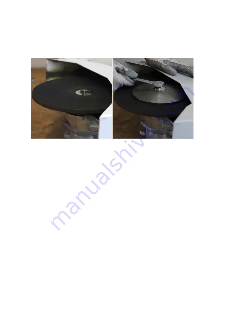
Figure 5 & 6: Change the cutting disc 


Summary of Contents for SR 310 H

Page 1: ...OPERATION MANUAL RAIL SAW SR 310 H ...

Page 2: ...RAIL SAW SR 310 H OPERATION MANUAL 2 ...

Page 3: ... 09 2018 08 08 2018 Creation In the table of contents maintenance was spelled wrong Pg 5 Issued a P N for the document Pg 10 note was spelled wrong Pg 15 Weight miss labeled as Height split Weight into two rows one for Saw only and one for Clamp only Updated Title Tables Added section 3 6 pg 14 Sven Kummer Jesse Bunn Garrett Lee Garrett Lee ...

Page 4: ...nce personnel 13 3 5 Emergency information safety devices 14 3 6 Safety signs 14 Table 2 Safety signs 14 4 Design and function 15 4 1 Design 15 4 2 Specification 15 Table 3 Specifications 15 4 2 1 Hydraulic fluid 16 Table 4 Hydraulic fluid data 16 Table 5 Suitable hydraulic fluids 16 4 2 2 Supply interfaces and connections 16 4 3 Function 16 4 4 Boundaries and interfaces 16 5 Transport assembly an...

Page 5: ...ng 24 8 1 General information for troubleshooting and repairs 24 8 2 Troubleshooting and repairs 24 Table 7 Troubleshooting 24 9 Shutdown and re commissioning 25 10 Storage 25 11 Dismantling and disposal 25 Publisher PortaCo Inc 1805 2nd Ave N Moorhead MN 56560 Phone 1 218 336 0223 Fax 1 218 233 5281 info portaco com www portaco com Date of publication 05 31 2018 Documentation version 1 0 Document...

Page 6: ...g company s specialized staff In addition to the operation manual the spare part catalogue and the maintenance manual of the manufacturers of the individual components are to be observed WARNING Operating errors using the device e g by instruction errors may lead to personal injury or damage to the device The instruction for use must be accessible to operators and maintenance personnel at all time...

Page 7: ...escribed in chapter 4 Regarding ergonomics the stresses and strains resulting from the device are typical for a device in the construction industry Because the Rail Saw is considered to be a complete machine according to the machinery directive 2006 42 EG an identification plate type plate is attached Figure 1 Identification plate 2 2 Designated use Rails which have already been mounted to the tra...

Page 8: ...y minimum distance must be observed around power lines and conductor rails When working in tunnels the country specific safety regulations must be observed 2 3 2 Emissions In technically perfect condition the A weighted emission sound level at the work place is lower than 70 dB A Hearing protectors is not required Other emissions do not occur during regular device operation In the event of damage ...

Page 9: ...ll persons who work on the device Introduction to the device is to be documented in writing CAUTION Hazards from the operational environment of the device can lead to injuries of persons No alterations to the device may be made which lead to a change in function All hazards from the environment or from unforeseeable operating conditions of the device cannot be captured and depicted within this man...

Page 10: ...ls 3 2 Important safety information Read this chapter and observe the safety information before using The safety regulations are to be observed by all persons who work on the device The regulations and instructions for accident prevention valid at the place of operation are to be observed Instruction of the operating and maintenance personnel in system safety is to be documented Please pay particu...

Page 11: ... operator or persons standing close by can be injured by sparks Highly flammable objects may ignite Wear flame retardant work clothing during work Remove highly flammable objects from the surrounding area DANGER The operator inhales aerosol of hydraulic oil Only use the device within the prescribed limits The device must be maintained at regular intervals the intervals are specified by the operato...

Page 12: ... work if visibility is poor WARNING The rail being worked on and the cutting disc are very hot There is a risk of severe burns if these are touched Allow the rail and the cutting disc to cool down after cutting Wear work gloves WARNING Improper maintenance or maintenance not carried out on time may result in damage to the machine or injury to persons Maintenance intervals are to be determined by t...

Page 13: ...here to the break and recovery times prescribed by law 3 3 Danger zone There is a danger of injury by cutting or sparks during operation of the Rail Saw The area around the cutting point and the cutting disc can become very hot Always operate the Rail Saw with the spark barrier Wear protective work wear while using the saw Allow the rail and the cutting disc to cool after using the saw 3 4 Qualifi...

Page 14: ...e equipment as intended In this case that means work gloves safety glasses or safety mask safety shoes S3 hearing protection 3 6 Safety signs Safety sign Meaning Mandatory sign Wear hearing protection indicates that while working with the machine hearing protection must be worn by all persons near to the machine Mandatory sign Wear safety glasses indicates that while working the machine safety gla...

Page 15: ... pump flow and return flow 3 Mounting base 4 Transport handle 5 Spark barrier 6 Cutting disc 4 2 Specification Criteria Value Width 686 mm 27 inch Length 1 143 mm 45 inch Height 457 mm 18 inch Weight Saw only 17 kg 39 lb Weight Clamp only 11kg 24 lb JB3 Hydraulic pressure max 150 bar 2 150 psi JB4 Hydraulic flow max 40 lpm 10 gpm Idle speed 4 800 U min rpm Table 3 Specifications ...

Page 16: ...Rails which have already been mounted to the track can be cut with the PortaCo Inc Rail Saw For this purpose the Rail Saw is mounted on the track Cutting discs with a diameter of 350 mm 14 and 400 mm 16 can be used with the saw It is possible to stand during sawing due to the long operating handle The saw is started as soon as the handle is pressed and stopped as soon as the handle is released An ...

Page 17: ...aw is equipped with transport handles Use the handles for transport 5 1 Mounting the blade Cutting discs with a diameter of 350 mm 14 or 400 mm 16 can be used with the Rail Saw When using bushings ensure that the bushings do not extend beyond the cutting disc Otherwise there is a danger that the safety mechanisms cannot properly hold the cutting disc 1 Remove the nuts and the dished spring Figure ...

Page 18: ...RAIL SAW SR 310 H OPERATION MANUAL 18 Figure 5 6 Change the cutting disc ...

Page 19: ...ydraulic power unit should have a flow rate of at least 38 liters per minute and ensure pressure between 100 bar and 140 bar respectively 40 gallons per minute and ensure pressure between 1 450 psi and 2 031 psi The pressure must be limited to 155 bar 2 248 psi The counter pressure of the hydraulic system should be less than 17 bar 247 psi measured at the return flow output of the Rail Saw The mea...

Page 20: ...2 1 Mounting onto rail 1 Mount the rail clamp on the rail Ensure that the clamp is in full contact with the rail Figure 7 Mounting the rail clamp 2 Mount the Rail Saw on the boom of the pedestal Figure 8 Mounting the Rail Saw on the pedestal ...

Page 21: ...t Ensure that the flow and return of the hydraulic unit are connected to the right quick couplings on the Rail Saw Figure 9 10 Connections of the hydraulic hoses 5 Start the hydraulic unit 6 Hold the saw tight with both hands 7 Loosen the locking mechanism and press the operating lever on the handle Figure 11 Actuating the throttle 8 After mounting a new cutting disc allow it to turn at full speed...

Page 22: ...e rail quickly and with uniform speed Do not reduce the speed of the cutting disc Do not hold the running cutting disc in the same position Figure 12 Operating the Rail Saw 10 Switch the hydraulic unit off 11 Depressurize the hydraulic power unit 12 Allow the hydraulic fluid to cool 13 Disconnect the flow from the Rail Saw 14 Disconnect the return from the Rail Saw 15 Protect the quick couplings w...

Page 23: ...age disturbing sounds overheating etc The machine must always be depressurized before maintenance work 7 1 Recommended maintenance plan Components for which wear and tear or even malfunction is determined during inspection must be repaired or replaced at the earliest possible date Components Inspection Intervals Entire device Cleaning The entire device must be cleaned with a lint free cloth at the...

Page 24: ...medy Cutting disc is not turning or turning to slowly Hydraulic fluid level too low Top off hydraulic fluid or replace Connection not airtight or loose Check connections and sealings and tighten or replace sealings Air in the device Bleed the system Mechanical error Check the entire device for damage Operating handle stiff Counter pressure too high 17 bar and 38 lpm should not be exceeded Device s...

Page 25: ...n to prevent corrosion Clean all external surfaces touch up paint damage and coat places prone to rust with a thin oil film Check for correct storage monthly 11 Dismantling and disposal Before dismantling or disposal the machine must be decommissioned This must be followed by draining the hydraulic fluid and properly disposing it Dismantling is to be carried out in the following order 1 Depressuri...

Reviews: