background image

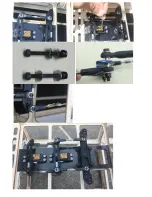
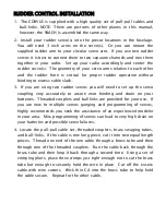
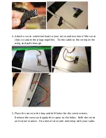
4. Attach a servo extension lead to your servo and use one of the servo

clips to secure the plugs together. Tie the cable to the string in the
wing and pull through.

5. Place the servo in the bay and drill holes for the servo screws.

Remove the servo and apply thin cyano to the holes. Refit the servo
and screw in place. Fit a metal servo arm centering with your radio.

Summary of Contents for Corvus Racer 540 120CC

Page 1: ...GoldWing RC Corvus Racer 540 120CC Giant Scale Aerobatic Aircraft...

Page 2: ...junction with EG AIRCRAFT EG Aircraft will exclusively sell in the USA while Goldwing RC will be available for the rest of the world Specifications of the aircraft are identical between the brands The...

Page 3: ...WORD ABOUT SAFETY AND RADIO CONTROL FLYING MODELS With radio control aircraft like any hobby or sport there are certain risks The operator of these models is responsible for these risks If misused or...

Page 4: ...MA information package call 1 800 435 9262 ext 292 or visit the AMA website at www modelaircraft org By the act of using the final assembled model the purchaser operator accepts all resulting liabilit...

Page 5: ...ct of using the final assembled model the user accepts all resulting liability If you should find any missing or damaged parts or have any questions about this product please contact within 30 days of...

Page 6: ...Replacement wheel tyres using the existing wheel hubs Flat nylon hinges for inproved flying strength Pre hinged control surfaces...

Page 7: ...Extra covering provided for small repairs genuine Ultracote Oracover Removable rudder Side force generators...

Page 8: ...CNC ALU canopy bolts X basla batten structure ensures high strength of fuselage Canopy hatch pins are made of nylon rods for better resistance aganist vibratio n...

Page 9: ...The Corvus is designed to directly accommodate KUZA rudder servo tray KUZA new 1000cc 34oz gas Tank with alloy tank cap included...

Page 10: ...Carbon Fiber accessories version Extra strength carbon fiber control horns...

Page 11: ...One piece airfoiled carbon fiber landing gear Carbon fiber tail wheel assembly with CNC machined metal parts including the aluminium tail wheel hub...

Page 12: ...Increased diameter carbon fiber wing tube over previous versions Two pcs carbon fiber tubes for stab Special 4in Painted carbon fiber spinner for Corvus...

Page 13: ...Scheme A White yellow black Scheme B Red white black...

Page 14: ...Scheme C White red black...

Page 15: ...s totaling at least 330 in oz or better Appropriate servo arms for the above Heavy duty servo wire extensions recommends two 42 two 18 three 12 two Y harnesses two 6 two 6 Two heavy duty switches with...

Page 16: ...scratch the covering surface Be sure you go over all seams and edges of the covering to assure it is secure to the airframe and other covering Be careful not to apply too much heat or you may cause bu...

Page 17: ...epoxy and coat the inside of the slots and the center of the control horns Hint a scrap piece of 1 16 ply tooth pick or old hobby blade can be used to coat the inside of the rudder slots Slide the co...

Page 18: ...f the flat hinges Install this end into the slots of the rudder and make sure each hinge is properly aligned at exactly 90 degrees to the hinge line 6 Now coat the other end of the flat hinges with ep...

Page 19: ...8 We recommend using KUZA 4 aluminium CNC servo arm sold separately for rudder control 9 We recommend using KUZA rudder servo tray available separately for better rudder performance...

Page 20: ...d so will be all other pending Goldwing airplanes that are 120cc or greater 11 You will need to provide 3X42 mm push rods 4 Pcs and ball links 8 Pcs depending on the servo of your choice 2Pcs KUZA 3 2...

Page 21: ......

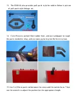
Page 22: ...yle linkage set 14 Cut off excess carbon fiber rudder horn and use sandpaper to rough the parts needed to inlay and use epoxy glue to glue the horn in place 15 Use 3x125mm push rod between the servo a...

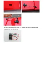
Page 23: ...16 We recommend using KUZA 1 75 aluminium CNC servo arm sold separately for rudder control...

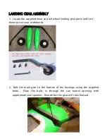
Page 24: ...il wheel landing gear parts and sort them out on your workbench 2 Bolt the main gear to the bottom of the fuselage using the supplied bolts Place the bolts in through the can tunnel opening with appro...

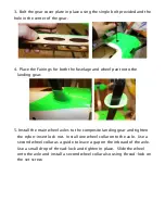
Page 25: ...g gear 5 Install the main wheel axles to the composite landing gear and tighten the nylon insert lock nut Install one wheel collar onto the axle Use a second wheel collar as a guide to leave a gap on...

Page 26: ...5 Fit the wheel pant in place and install using the two supplied bolts Use thread lock to secure the bolts in place Repeat the above steps for the other main gear...

Page 27: ......

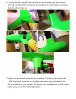
Page 28: ...d leave for a few hours to ensure that the silicon has set 7 Begin the tail wheel assembly by installing Tail wheel assembly with CNC machined metal parts including the aluminum tail wheel hub The ins...

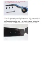
Page 29: ...s on the fuselage use a knif e to open the Oracover then use three screws to attach the carbon plate to the fuselage using thread lock Then install the spring using the self tapping screws to attach t...

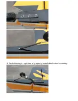
Page 30: ...9 The following is a picture of properly installed tail wheel assembly...

Page 31: ...oupling very accurately to assure zero binding and drain on your batteries Threaded couplers and ball links are provided for your use If you are new to multiple servos ganging and programming of servo...

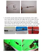
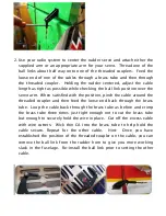
Page 32: ...horn first to make this step easier and then re install once the couplers are threaded on Feed the loose end of each cable into the cable slots at the rear of the fuselage and feed them forward towar...

Page 33: ...sition pinch the cable around the threaded coupler and then feed the loose end back through the brass tube Loop the cable back through the brass tube as before and crimp the brass tube three times jus...

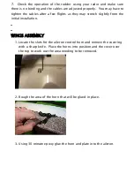
Page 34: ...hey may stretch slightly from the initial installation WINGS ASSEMBLY 1 Locate the slots for the aileron control horn and remove the covering with a sharp knife Place the horns into position and the c...

Page 35: ...ecure the plugs together Tie the cable to the string in the wing and pull through 5 Place the servo in the bay and drill holes for the servo screws Remove the servo and apply thin cyano to the holes R...

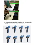
Page 36: ...6 Usinf the pushrods connect the servo arm to the horn Remember that the pushrod one end that is reverse threaded...

Page 37: ...Use M3 bolts and nuts to connect the pushrod Set it so the aileron it level when the arm is at 90 degrees 7 We recommend using KUZA 1 75 aluminium CNC servo arm sold separately for wing control...

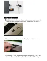
Page 38: ...remove the covering where the horns are inserted and the area for the plate 2 Sand the area on the horn that will be glued inside the elevator 3 Using plenty of 30 minute epoxy fit the horn and plate...

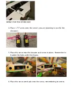
Page 39: ...1 75 arms onto the servo s you are planning to use for the elevators 5 Place the servo into the elevator and screw in place Remember to harden the holes with thin Cyano 6 Place the servo arm back ont...

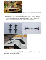
Page 40: ...place remembering one end is reverse threaded Set it so the arm is centered and the elevator is flat Choose the holes depending on how much deflection you require 8 We recommend using KUZA 1 75 alumi...

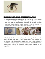
Page 41: ...he engine center line is offset to the left to compensate for the right thrust built into the engine box 2 Fit the Cowl and measure the distance from the engine bulkhead to the front of the cowl add a...

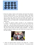
Page 42: ...mended for the engine bolts 4 Mount the ignition module according to the manufacturer s instructions The best place to mount it is on the side or top of the engine box Secure the pickup lead and ignit...

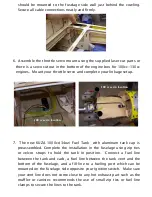
Page 43: ...tank cap is preassembled Complete the installation in the fuselage using zip ties or velcro straps to hold the tank in position Connect a fuel line between the tank and carb a fuel line between the ta...

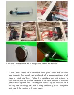
Page 44: ...be closed off to accept canisters of all sizes or stock mufflers Follow the manufacturer s instructions for your exhaust system paying attention to vibration mounts if required and air flow requiremen...

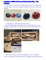
Page 45: ...le in three colors black red and blue 2 Installation of KUZA CNC Aluminum Fuel Dot Sites for KUZA fuel dot installation are pre cut on both sides of the fuselage you may install it on either side Use...

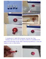
Page 46: ...of KUZA CNC Aluminum Fuel Vent Line Plug Similarly two sites for vent line plug installation are available at the bottom of the fuselage Secure KUZA vent line plug with four 2 5 mm self tapping screws...

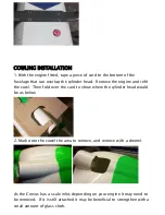
Page 47: ...engine and refit the cowl Then fold over the card to show where the cylinder head would be as below 2 Mark onto the cowel the area to remove and remove with a dremel As the Corvus has a scale inlet de...

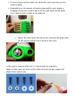
Page 48: ...louvers in the bottom of the cowl has been provided Use a dremel tool to remove the material When the cowl clears the engine etc correctly the prop shaft of the engine will be in the centre of the co...

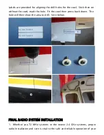
Page 49: ...he cowl mark the hole Fit the cowl then press back down The hole will then show the area to drill Sere below FINAL RADIO SYSTEM INSTALLATION 1 Whether you 72 MHz systems or the newer 2 4 GHz systems p...

Page 50: ...nd then use zip ties or velcro straps to secure them tightly in place 5 Servo and battery leads are the life blood of your aircraft Make sure all wires are top quality and connectors are tight and dis...

Page 51: ...d maintain level flight with very little to no down elevator input If the aircraft climbs when inverted then you ve probably got your CG too far aft If the nose drops more than slightly then you are m...

Page 52: ...ur batteries are fully charged and all radio systems are in working order 2 Installation of the rudder The rudder is removable for convenience in transportation it is connected to fuselage by insertin...

Page 53: ...Hook up the tail wheel spring 3 Installation of Elevators Connect servo extension wire secure with safe clips Attach elevators with 3x12mm Hex head bolts and washers Check these after every flight...

Page 54: ...de your servo wires into the fuselage openings and connect to the correct aileron channels Servo clips are highly recommended Once you have the wings fully seated in the fuselage tighten the wing bolt...

Page 55: ...e your vent line is not plugged or capped With the canopy off this is a good time to check for any fuel leaks 7 Position the canopy in place and tighten ALU Canopy Bolts Be sure to use the supplied PT...

Page 56: ...9 Check your batteries and perform a range check once again with the engine off and running Be sure all surfaces are moving in the correct direction and the correct amount for your flying setup 10 You...

Page 57: ...UZA CNC Aluminum Fuel Dot 3 color to choose black blue red No KAG0231B or KAG0231U or KAG0231R KUZA CNC Aluminum Fuel Vent Line Plug 3 color to choose black blue red No KAG0232B or KAG0232U or KAG0232...

Page 58: ...KUZA Fuel line clips 10PCS No KAG02454 KUZA 1x servo tray No KAG0T01 KUZA Heavy duty 7075 aluminum Servo Arm For Futaba servo 25T 47mm 1 75in Single No KAG0S7F 100mm 4in Dual No KAG0D723F...

Page 59: ...24T 47mm 1 75in Single No KAG0S7H 100mm 4in Dual No KAG0D73H For JR servo 23T 47mm 1 75in Single No KAG0S73J 100mm 4in Dual No KAG0D73J KUZA new Wingbag for 120CC Two color to choose red black blue si...

Page 60: ...GoldWing RC www goldwingrc com...

Reviews: