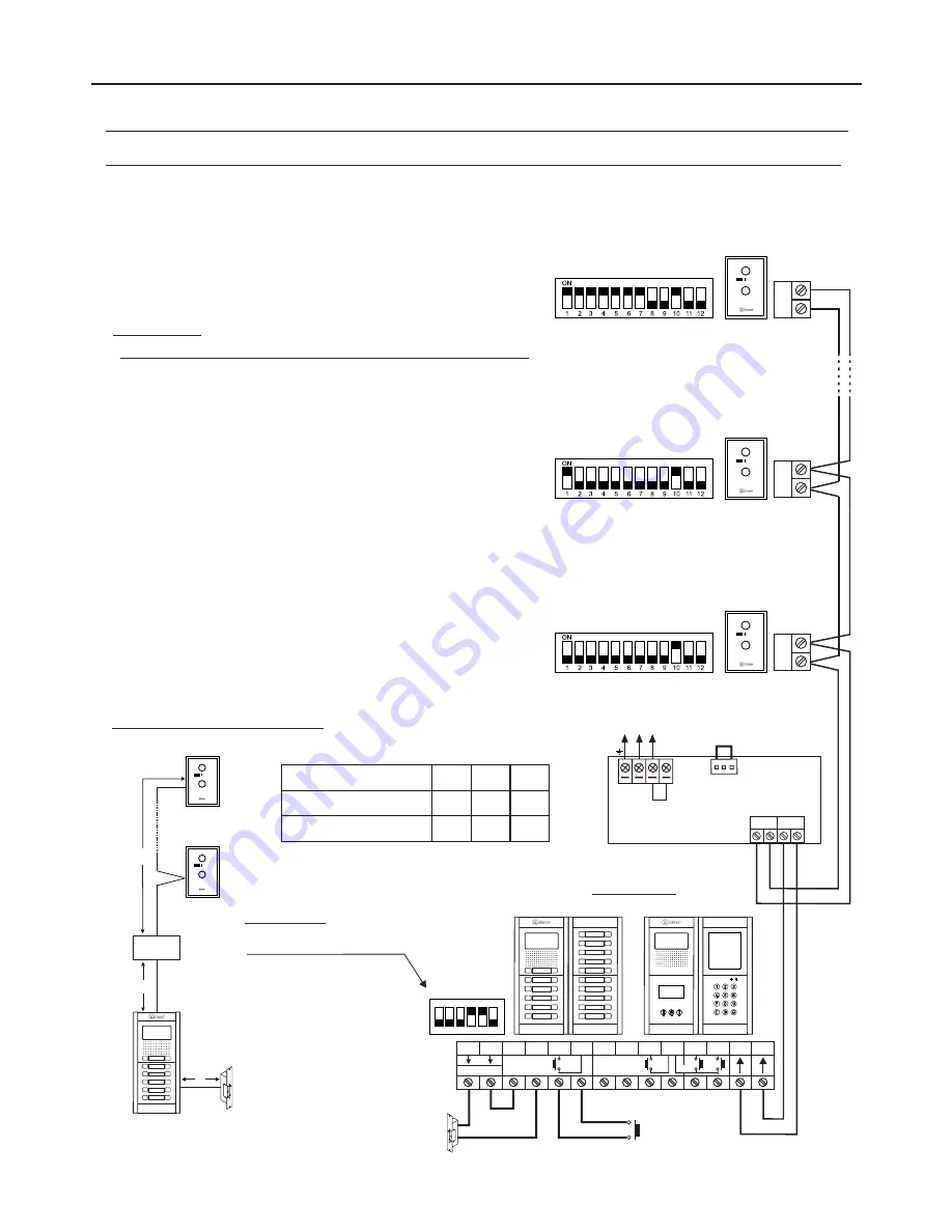
WIRING DIAGRAMS
Audio door entry system with 128 apartments/NHEA GB2 terminals and Golmar DC lock release:
NA2
+
AP-
C1 NA1
AP+
C2 AP+ AP- P1 P2 BUSBUS
Relay 2
Relay 1
_
12Vdc
Lock release
max. 12 Vdc/270mA.
AP
APARTMENT
1
Twisted pair 2x0.75mm
2
Twisted pair 2x1mm
2
60m
A
60m
B
80m 80m
Cable
10m
C
15m
*
( )
*
( )
Distances and cross-sections:
A
C
B
APARTMENT
2
APARTMENT
128
FA-
2
GB /A
Mains
100~240Vac
N
L
CN
BUS (M) BUS(PL)
FA-
2
GB /A
L
Button panel
ON
1 2 3 4 5 6
SW1
Access panel
or
Coded panel
*
( )
( )
*
( )
For more information about the door panel, installation, con
fi
guration, connection of an AC lock release, 2nd lock release or mixed installation
with monitors and Nhea terminals, see the corresponding door panel manual.
IMPORTANT: Set the
DIP switches as shown
in the diagram.
*
( )
Telephone only
button mode
or
telephone only
coded mode
*
( )
( )
IMPORTANT:
-
Up to 128 apartments/Nhea terminals per 'audio only' installation:
El632 GB2A/EL642 GB2A
sound module required and button
panel must be set to 'operating mode 2' or coded panel to
'operating mode 6'.
-
The Nhea terminal's DIP 10 should be set to ON.
1
( )
( )
1
( )
( )
1
( )
( )
1
( )
( )
14
NHEA GB2 HANDS-FREE AUDIO TERMINAL
AUX
NHEA
AUX
NHEA
NHEA
Master
AUX
NHEA
Master
AUX
NHEA
Master
AUX
*
( )
*
( )
*
( )
BUS
BUS
BUS


