6
CONFIGURATION
onfiguration of the repeater.
C
"Uno" units connected to input and output.
"Plus" units connected to input and output.
"Uno" units connected to input and "Plus" units connected to output.
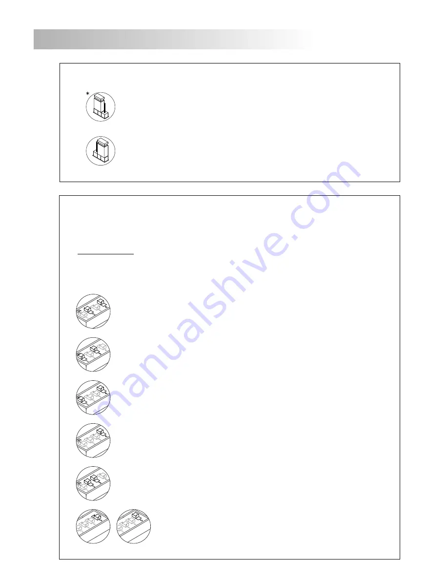
Use dip-switches
Sw1
,
Sw2
and
Sw3
to configure the repeater.
"Plus" units connected to input and "Uno" units connected to output.
Installation with "Plus" General door panels and "Uno" Inner door panels, configure
with this mode
only the repeater of the first "Uno" Inner door panel
.
"Plus" units connected to input and "Uno" units connected to output.
Installation with "Plus" General door panels and "Uno" Inner door panels, configure
with this mode
the repeater of the next "Uno" Inner door panel
.
Placed to OFF, the repeater is configured as audio separator mode.
Set to ON, the repeater is configured as audio separator mode with
capacitance compensation of the audio line. (See configuration dip-
switches
Sw1
and
Sw3
, page 34).
Depend on the type of units connected to the repeater and the function mode of the audio
separator (separator or separator with capacitance compensation of the audio line).
Dip-switch Sw2:
Continue
escription of the configuration jumper.
D
On
Off
JP1
JP1
Resistencia final de línea.
Set to Off if does not end the video cable (coaxial) in the "BUS1" side of the digital
repeater.
End of line resistor.
Set to On if the video cable (coaxial) ends in the "BUS 1" side of the digital repeater.
*Factory default
*Factory default
*


