78
77
DOOR PANEL INSTALLATION
DOOR PANEL INSTALLATION
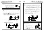
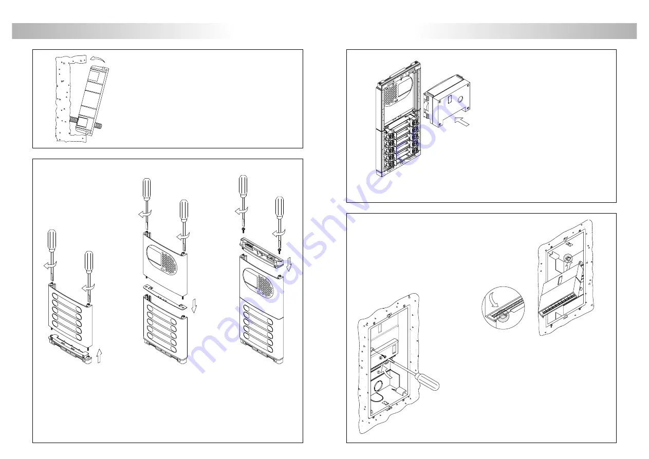
To assembly the EL516 encoder, screw the top tab
of the case to the corresponding plastic lug
of the embedding box.
In case of more than one encoder, place them underneath
or in the next embedding box.
The use of EL516 encoders is only necessary for panels
with more than 8 push buttons.
Each encoder allows to connect 15 push buttons,
obtaining a maximum of 120 push buttons by using
8 encoders.
1
2
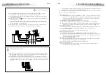
lace the embedding box.
P
Pass the wiring through the hole made in the bottom part
of the embedding box. Level and flush the embedding
box. Once the embedding box is placed, remove the
protective labels from the attaching door panel holes.
ssembly the door panel modules.
A
Insert the header DOWN marked in the lower module and fix it by screwing the module
shafts.
Place the module spacer between lower and next modules, assuring that the spacer
adjustment notches are inside the panel. Fix the module by screwing the shafts.
Repeat this procedure in case of door panels with one more module (the maximum
number of modules placed vertically is three).
Insert the header UP marked in the last module and fix it by screwing the supplied screws.
ssembly the sound module.
A
Insert the sound module in the grille module.
For a proper assembly, align the light
push button and the microphone rubber
of the sound module with its corresponding
holes in the grille module.
ssembling the EL500 microprocessed circuit
and the EL516 push buttons encoders.
A
The EL500 circuit is to be assembled on the top
of the embedding box. Insert the circuit in
the top flanges of the embedding box (1).
Push-in the circuit in the bottom flanges (2)
by pressing the pcb board.


