84
83
DOOR PANEL INSTALLATION
DOOR PANEL INSTALLATION
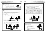
Jumper JP1 loads the installation with a communications
resistor. For a proper system operation, activate this resistor
only in the closest door panel to the backbone installation
or in the general entrance door panel (if exists).
Factory default: enabled.
Jumper JP2 selects the type of cable to be used for the video
signal: coaxial cable (RG-59 or RG-11) or twisted pair.
Twisted pair video transmission requires the use of an
EL560 module plugged in the CN4 connector.
Factory default: coaxial cable.
Jumper JP3 selects the volume of the door panel acknowledgement
signals (call in progress, system busy and door opened).
If after starting the system it's considered that the volume is too
high, modify the jumper position.
Factory default: maximum.
Jumper JP4 selects if the door panel has telecamera or not.
In case of door panels without telecamera
(EL540 sound module), change the jumper position.
Factory default: with camera.
Enabled.
Disabled.
Coaxial.
Twisted pair.
Maximum.
Minimum.
With camera. Without camera.
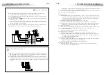
inary coding of the configuration dip switch.
B
The switches set to OFF have null value. The values of the switches
set to ON are shown in the enclosed chart.
The building code will be calculated as the sum result of the
switches values set to ON.
Example: 64+0+16+0+4+2+1=87
Switch number:
ON value:
4
64
5
32
6
16
7
8
8
4
9
2
10
1
ptional. EL560 module for video installations
O
with twisted pair cable.
Plug the EL560 module in the CN4 connector.
The CN4 connector is accessible by opening
the terminal connector protection cover.
NOTE: on this type of installations the EL562 module
must be plugged in all the monitors and JP2
jumper of the EL500 circuit must be placed
on the position specified on page 83.
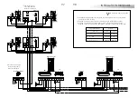
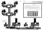
Refer to the specific installation diagram.
escription of the configuration dip switch.
D
Set to ON the switch number 2 for monitor or telephones
programming. Once the programming progress is finished
return the switch to OFF position. The programming process
is described on pages 92 (monitors) and 95 (telephones).
Set to OFF the switch number 3 in case of a master door panel.
Each system must have only one master door panel; the rest
must be slaves (ON). In systems with general entrance panel
set as master one door panel of each internal building.
Switches number 4 to 10 set the building code. In systems with several
door panels, set the same code in all the panels; in systems with
general entrance panel, set different codes for each internal building.
Valid codes are from 0 (factory default) to 99. To set the code use
binary coding as shown on the next paragraph.
Coming from previous page
escription of the configuration dip switch.
D
The SW1 configuration dip switch is accessible by opening
the terminal connector protection cover.
Switch number 1 allows to activate the autoswitch-on function
(audio and video communication without previous call)
at the door panel that has this switch to ON position.
In systems with several door panels activate this function
only in one of them; in systems with general entrance panel
this function can be activated in one door panel of each
internal building.
Continue
escription of the configuration jumpers.
D
The JP1, JP2, JP3 and JP4 configuration jumpers
(from left to right respectively) are placed on the
left side of the EL500 circuit, and are accessible
by opening the terminal connector protection cover.


