background image


-

21-


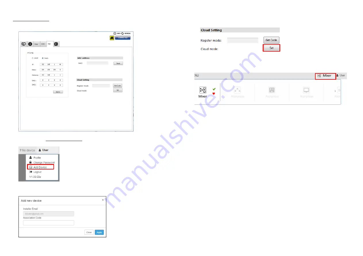
Add Device to Eagleyes 

1.


Firstly, please make sure the device is connected to the Ethernet. Then please executing the 
software with device to get the register code (Note: the status of software is connected). 


2.


Access Eagleyes (http://www.eagleyes.io), and then log in your account on the right top corner. 
Click 

Add device

 to add the device which you just got its association code. 


3.


Enter the Installer Email for online support in the future, and the Association Code for pairing with 
your device. 


-

22-


4.


Click the “SET” button on software to reset cloud 


5.


After adding the device, the list of device related to your account will show on the right top corner. 
You can click the button to switch device for control. 


Summary of Contents for MX-5004MZ2F

Page 1: ...Processor with 4K2K60 4 4 4 User Manual rev 201214 Made in Taiwan TABLE OF CONTENTS INTRODUCTION 1 FEATURES 1 PACKAGE CONTENTS 1 SPECIFICATIONS 2 PANEL DESCRIPTIONS 3 CONNECTION DIAGRAM 4 HARDWARE INSTALLATION 4 OPERATION APPROACH 5 WARRANTY 23 ...

Page 2: ...gital HDMI Software control through RS 232 and Ethernet Supports IR remote and front panel control Supports Cloud Control PACKAGE CONTENTS 1 x MX 5004MZ2F 1 x DC 12V 5A 1 x Installation software CD 1 x User Manual 1 x IR Remote control 28 keys 1 x IR Receiving cable Cloud support is thru an encrypted communication to provide the best private protection when using MX 5004MZ2F 2 SPECIFICATIONS Model...

Page 3: ...eceiver 3 5mm socket for plugging in the extension cable of IR receiver 10 SOURCE 1 4 HDMI inputs 11 Stereo audio output L R 12 OUTPUT 1 2 HDMI outputs 13 RS 232 RS 232 control port 14 Ethernet Ethernet control port 15 Micro USB For F W update The MX 5004MZ2F is able to automatically downscale on output 2 according to EDID of connected display equipment 4 CONNECTION DIAGRAM HARDWARE INSTALLATION M...

Page 4: ... Select source D to be the input source C Select source C to be the input source B Select source B to be the input source A Select source A to be the input source P4 User preset 4 P3 User preset 3 P2 User preset 2 P1 User preset 1 6 Method B Software Control through Micro USB port 1 System Requirement 1 OS Information MS Win XP 7 8 10 2 Baud rates 115200 3 Software size 10 MB 4 Minimum RAM require...

Page 5: ...n to change 1 2 3 4 5 6 7 9 8 8 2 Output Settings In this section users can set up the coordinate for inputs the source of window A D output resolution layout setting PAP or full screen and switch mode 1 Source Selection For each display window you can assign arbitrary video source here 2 Quick Selection We provide 9 default modes 8 custom modes and 4 switching effects Seamless Fade in out Dissolv...

Page 6: ... addition we provide display ratio for users to set the display panel sizes If you want to change window layer please drag window icon in Layer Control section 10 3 Advanced Setting 1 Label Text In here users can input the texts to be shown with the video 2 Sound To set up the audio source of the output and R L channels Audio Mode Fixed The audio source of the output and R L channels will fix to b...

Page 7: ...ite this picture into the device 5 HDR Control To Enable Disable HDR 12 4 Crop Setting If users want to use Crop mode remember to set the window A D to the same video source in the Source Selection of the Connection Status page 1 Visible Window Control Users can customize the display mode thru control First Select the input windows to be displayed on output1 and output2 on the right Then adjust th...

Page 8: ...ter setting the crop range please click the Enable Crop and the OK button 3 To get the width height of source information Users can get the width height of source 1 4 information as a reference for the cutting range The image below shows an example of using Crop mode 14 5 EDID Extended display identification data Learn EDID from Default or Display Select EDID Select Input Click button to learn EDI...

Page 9: ... button to automatically get the IP address IP Configure Static mode Select Static and then key in the IP MASK GATEWAY information After the step of IP configuration please click the button The setup of Ethernet for the unit as below example shows 16 2 MAC address MAC Read the device s MAC address information 3 Cloud Setting Register mode To get an association code The device can use this code to ...

Page 10: ...to connect device Click update button to do firmware update 2 Factory Reset Click button to do factory default reset The process of default reset will take about 25 seconds 8 Info Read the Software and firmware version Software firmware information subject to change without notification 9 Refresh This function can get all information of the device and update this software state ...

Page 11: ... The password of Admin admin 20 Method D Cloud Control Eagleyes through Ethernet Port Create Account The first time to use the Eagleyes service please create a new account 1 Access Eagleyes http www eagleyes io and click Create new account 2 The Registration page will pop up and please fill in your email and password information to create your private account ...

Page 12: ...d then log in your account on the right top corner Click Add device to add the device which you just got its association code 3 Enter the Installer Email for online support in the future and the Association Code for pairing with your device 22 4 Click the SET button on software to reset cloud 5 After adding the device the list of device related to your account will show on the right top corner You...

Page 13: ...e the unit or assume the risk of loss or damage in transit Under no circumstances will a unit be accepted without a return authorization number The warranty is in lieu of all other warranties expressed or implied including without limitations any other implied warranty or fitness or merchantability for any particular purpose all of which are expressly disclaimed Proof of sale may be required in or...

Reviews: