background image

Mode d‘emploi

34

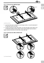
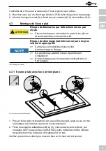
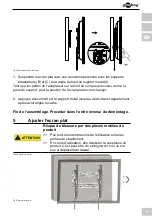
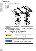
4.3.2   Ecrans plats avec face arrière courbée


Fig. 15: Ecrans plats avec face arrière courbée


1.   Excepté pour l‘étape suivante - procédez comme indiqué dans le chapitre  

 4.3.1.

2.   Montez les entretoises d’ajustement TV (M-G) et/ou (M-H) entre les sup 
  ports d‘adapteur (B) / (C) et l’écran plat tel qu’indiqué.

4.4

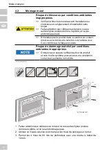
        Assembler et fixer l‘écran plat

Risque de blessures par trébuchement ou par 

chute

>>

>>

Placez, transportez et installez le produit, les pièces 

et les accessoires en toute sécurité.

Laissez uniquement un spécialiste effectuer les opé-

rations de démontage, d‘entretien et de réparation. 

Risque de dommage matériel par conditions 

ambiantes inappropriées

>>

Conservez un espace suffisant autour du produit 

et vers tout le système pour assurer une ventilation 

correcte et permettre la mobilité. 

Tab. 27:

 Assembler et fixer l‘écran plat


Summary of Contents for 67821

Page 1: ...DE EN FR IT BETRIEBSANLEITUNG USER S MANUAL MODE D EMPLOI ISTRUZIONI PER L USO TV Wandhalter TV wall mount TV Support mural Supporto per TV 67822 TV EasyFlex L2 67821 TV EasyFlex XL2...

Page 2: ...1 Vorbereitung 7 4 2 Wandmontage 7 4 3 Flachbildschirmmontage 8 4 3 1 Flachbildschirme mit flacher R ckseite 9 4 3 2 Flachbildschirme mit gew lbter R ckseite 9 4 4 Einh ngen und Sichern des Flachbild...

Page 3: ...Personen verletzen Produkt Produktteile und Zubeh r sicher platzieren installieren und transportieren Bei Arbeiten mit Lasten sich und den Arbeitsort sichern und von zweiter Person helfen lassen Demon...

Page 4: ...tz f r gute Bel ftung und Beweglichkeit lassen Das mitgelieferte Montagematerial ist ausschlie lich f r die Montage an massiven Stein und Betonw nden geeignet Bei abweichender Beschaffenheit geeignete...

Page 5: ...rms an stabilen vertikalen W nden Die kompakte und flache Bauweise unterst tzt ein individuelles platz sparendes Anbringen Nach dem Montieren ist der Wandhalter nahezu unsicht bar Er ist neigbar aber...

Page 6: ...gscheibe M F 4 TV Abstandhalter M G 8 TV Abstandhalter M H 4 Tab 2 Lieferumfang 2 2 ben tigtes Werkzeug Werkzeug Abbildung Leitungspr fer Wasserwaage Stift Kreuzschlitz Schraubendreher Bohrmaschine Be...

Page 7: ...gs auf Vollst ndigkeit und Unversehrtheit kontrollieren Kompatibilit t sicherstellen Sachschaden durch inkompatible Produktkombi nationen Technische Daten aller verwendeter Produkte ver gleichen Diese...

Page 8: ...e jeweils einen Wandd bel W B in die Bohrl cher 5 Bringen Sie den Wandhalter A mit den Wandschrauben W A und den Unterlegscheiben W C an 4 3 Flachbildschirmmontage Verletzungsgefahr durch Stolpern und...

Page 9: ...Umkippen 2 Montieren Sie die Adapterhalterungen B und C jeweils mit den Schrauben M A den Unterlegscheiben M F bzw mit den Schrauben M B M C ohne Unterlegscheiben wie abgebildet jeweils an der Ger teo...

Page 10: ...durch ungeeignete Umgebungsbe dingungen Um Quell und Ausgabeger te sowie um Schwenk und Neigebereich ausreichend Platz f r gute Bel f tung und Beweglichkeit lassen Fig 4 Einh ngen und Sichern des Fla...

Page 11: ...6 Pflege Wartung Lagerung und Transport Das Produkt darf nur von einer Fachwerkstatt gewartet werden Sch tzen Sie die Gelenke vor Schmutz und schmieren Sie diese regelm ig mit leichtem Maschinen l Re...

Page 12: ...f r den Transport auf um Sch den zu ver meiden 7 Problembehebung Problem Hilfe Wie kann die Wandqualit t getestet werden Verkehrslasten f r Wohnr ume sind in diversen Europa richtlinien festgelegt Wan...

Page 13: ...stufenlose individuelle Befestigung zu z B 300 x 300mm f r Sony TVs VESA Klasse Befestigungslochabstand von Flachbildschirmen MIS D 75x75 100x100mm MIS E 200x100 200x200mm MIS F 400x200 400x400 600x2...

Page 14: ...red tools 18 3 Intended Use 19 3 1 Use restrictions 19 4 Installing 19 4 1 Preparing 19 4 2 Wall mounting 19 4 3 Mounting the flat screen 20 4 3 1 Flat screens with flat back 21 4 3 2 Flat screens wit...

Page 15: ...e way When working with burdens secure yourself and the working place let a second person help you Let only a specialist do disassembly maintenance and repair work Risk of injury by cutting Children c...

Page 16: ...mounting material Check the stability of the system periodically after installation 1 2 User Groups Caused to different risk levels and hazard potentials some working steps only may be done by traine...

Page 17: ...vertical walls The compact and slim design supports individual space saving mounting It is tiltable but not swivelable 2 1 Scope of Delivery Part Figure Symbol Amount Wall mounting Wall mount A 1 Wal...

Page 18: ...Washer M F 4 TV Spacer M G 8 TV Spacer M H 4 Tab 11 Scope of Delivery 2 2 Required tools Tool Figure Line tester Spirit level Pencil Phillips screwdriver Drilling mashine Concrete drill 8x60mm Second...

Page 19: ...omparing it to the scope of delivery regarding completeness and integrity Ensuring compatibility Risk of material damage by improper product combination The specifications of all used products must ma...

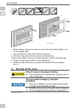
Page 20: ...4 Plug a concrete anchor W B in each drilling hole 5 Mount the wall mount A by using the wall screws W A and washers W C 4 3 Mounting the flat screen Risk of injury by tripping and falling Place tran...

Page 21: ...or a wall and protect it of scratches and overturning 2 Install the adapter brackets B and C by using the fitting screws M A with or M B M C without washer M F on the top and bottom side as shown Mak...

Page 22: ...material damage by inappropriate ambi ent conditions Keep enough space around product and to the whole system to ensure proper ventilation and mobility Tab 16 Attaching and locking the flat screen Fig...

Page 23: ...e angles from dirt and grease them regularly with light machine oil Use a dry and soft cloth to clean your product Be careful to avoid scratches Use a slightly moist cloth for heavy stains Look out fo...

Page 24: ...ss and material under plaster wall paper Ask a specialist Which drill holes must be drilled Read chapter 4 2 The wall mount is hard to align Carefully loosen both screws at the top Other questions Con...

Page 25: ...attachment of monitors MIS D 75x75 100x100mm MIS E 200x100 200x200mm MIS F 400x200 400x400 600x200 600x400 800x400mm Tab 20 Information for VESA standard 10 Disposal Instructions This product should n...

Page 26: ...29 2 2 Outils requis 30 3 Utilisation pr vue 31 3 1 Restrictions d utilisation 31 4 Installation 31 4 1 Pr paration 31 4 2 Montage mural 32 4 3 Montage de l cran plat 33 4 3 1 Ecrans plats avec face...

Page 27: ...its inappropri s peuvent entra ner des blessures Placez transportez et installez le produit les pi ces et les accessoires en toute s curit Quand vous travaillez avec des charges travaillez en s curit...

Page 28: ...space suffisant autour du produit et vers tout le syst me pour assurer une ventilation correcte et permettre la mobilit Le mat riel de montage fourni convient uniquement au montage sur de grosses pier...

Page 29: ...fonction Votre montage mural est con u pour installer votre cran plat sur des murs verticaux stables Le design compact et fin soutient le montage individuel permettant d conomiser de l espace Apr s ce...

Page 30: ...M C 4 M6x30 M D 4 M8x30 M E 4 Rondelle M F 4 Rondelle d espacement TV M G 8 Rondelle d espacement TV M H 4 Tab 22 Contenu de la livraison 2 2 Outils requis Outil Figure Testeur de ligne Niveau bulle...

Page 31: ...urit peuvent causer de graves accidents des blessures et des dommages mat riels Reportez vous aussi au chapitre Garan tie et responsabilit 3 1 Restrictions d utilisation Utiliser uniquement dans des l...

Page 32: ...la lumi re du soleil ou la lumi re vive Ceci contribue la fatigue oculaire Risque de dommage mat riel par conditions ambiantes inappropri es Conservez un espace suffisant autour du produit et vers tou...

Page 33: ...t pour viter d endommager le filetage Ne positionnez JAMAIS l cran devant durant l installation N endommagez pas l cran plat en utilisant des vis trop longues Tab 26 Montage de l cran plat 4 3 1 Ecran...

Page 34: ...sembler et fixer l cran plat Risque de blessures par tr buchement ou par chute Placez transportez et installez le produit les pi ces et les accessoires en toute s curit Laissez uniquement un sp cialis...

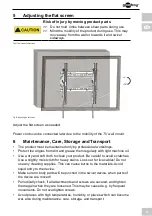
Page 35: ...2 Appuyez doucement sur le support mural jusqu au d clic dans l appartement apr s avoir align le cadre Fin de l assemblage Proc der dans l ordre inverse du d montage 5 Ajuster l ecran plat Risque de...

Page 36: ...sont d plac es V rifiez r guli rement que toutes les fixations et vis sont bien solidement ancr es resserrez les lorsqu elles sont desserr es Ceci peut tre provoqu par exemple par les mouvements fr qu...

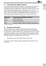
Page 37: ...oir Dimensions 67821 40x654x435 67822 40x504x435 mm Poids 67821 3 03 67822 2 71 kg Tab 30 Sp cifications 9 Informations sur la norme VESA Pour harmoniser de fa on conviviale les options de branchement...

Page 38: ...s m nagers Veuillez d posez gratuitement votre appareil en fin de vie un point de r cup ration des d chets destin cet effet ou aupr s de votre point de vente Les d tails concernant la mise au rebut so...

Page 39: ...39...

Page 40: ...sari 44 3 Scopo d utilizzo 45 3 1 Limitazioni d uso 45 4 Installazione 45 4 1 Preparazione 45 4 2 Installazione su parete 45 4 3 Installazione dello schermo piatto 46 4 3 1 Schermi piatti con fondo pi...

Page 41: ...appropriato possono provocare lesioni alle persone Collocare trasportare ed installare il prodotto sue parti ed accessori in modo sicuro Quando si lavora con pesi proteggere s stessi ed il luogo di la...

Page 42: ...e un adeguata ventilazione e la mobilit Il materiale d installazione fornito in dotazione adatto solo per l installazione su pietra massiccia o pareti di cemento Per altri tipi di pareti usare kit d i...

Page 43: ...li Il design compatto e sottile supporta l installazione individuale ed in economia di spazio Il supporto a parete praticamente invisibile inclinabile ma non ruotabile 2 1 Scopo della consegna Parte F...

Page 44: ...F 4 Distanziatore TV M G 8 Distanziatore TV M H 4 Tab 33 Scopo della consegna 2 2 Strumenti necessari Strumento Figura Tester di linea Livella a bolla Matita Cacciavite a stella Trapano Trapano per c...

Page 45: ...rit Controllare il contenuto della confezione e confrontarlo con i Contenu ti della confezione per quanto riguarda la completezza e l integrit Garantire la compatibilit Rischio di danni materiali caus...

Page 46: ...i fili che si trovano dietro l intonaco e non danneggiarli 2 Utilizzare una livella a bolla per segnare i punti dove forare la parete 3 Praticare i 4 fori profondi 60 mm con un trapano da cemento e pu...

Page 47: ...e dello schermo piatto 4 3 1 Schermi piatti con fondo piatto Fig 19 Schermi piatti con fondo piatto 1 Appoggiare lo schermo piatto in verticale su una superficie morbida e di grandi dimensioni oppure...

Page 48: ...sicurare dello schermo piatto Pericolo di lesioni da incespicamento e caduta Collocare trasportare ed installare il prodotto sue parti ed accessori in modo sicuro Quando si lavora con pesi proteggere...

Page 49: ...atto ancora cambiare 2 Premere delicatamente contro il supporto a parete finch non scatta in l appartamento dopo aver allineato il telaio Fine del installazione Procedere in ordine inverso rispetto su...

Page 50: ...on usare alcun prodotto detergente Questi provocano bruciature ai materiali Evitare che i liquidi penetrino nel dispositivo Assicurarsi che nessuna parte del corpo possa impigliarsi nel dispositivo gi...

Page 51: ...ono essere eseguiti Leggere il capitolo 4 2 Il kit per l installazione a parete difficile da allineare Allentare con cautela le due viti nella parte superiore Altre domande Rivolgersi al rivenditore T...

Page 52: ...tor MIS D 75 x 75 100 x 100 mm MIS E 200 x 100 200 x 100 mm MIS F 400 x 200 400 x 400 600 x 200 600 x 400 800 x 400 mm Tab 42 Informazioni sullo standard VESA 10 Istruzioni sullo smaltimento Questo pr...

Page 53: ...53...

Page 54: ...Istruzioni per l uso 54...

Page 55: ...55...

Page 56: ...Support mural Supporto per TV 67821 67822 Revision 2014 11 18 Version 1 1 Goobay by Wentronic GmbH Pillmannstra e 12 38112 Braunschweig Germany Made in China Hotline 49 0180 5005882 E Mail info goobay...

Reviews: