background image


viii 

9.7


Output Voltage Stability

 .................................................................................................... 214


9.8


Distortion of Output Voltage Waveform

 ............................................................................. 214


9.9


Power Input

 ...................................................................................................................... 214


9.10


Withstand Voltage and Insulation Resistance

 ..................................................................... 215


9.11


Measurement Function

 ..................................................................................................... 215


9.12


Power Unit Energization Setting

 ........................................................................................ 217


9.13


Current Limiter

 ................................................................................................................. 218


9.14


Setting Range Limit Function

 ............................................................................................. 218


9.15


Remote Sensing

 ................................................................................................................ 219


9.16


AGC

 ................................................................................................................................. 219


9.17


Autocal (Output Voltage Compensation)

 ............................................................................ 220


9.18


Sequence

 .......................................................................................................................... 221


9.19


Simulation

 ........................................................................................................................ 221


9.20


Clipped Sine Wave

 ............................................................................................................ 222


9.21


Arbitrary Wave

 .................................................................................................................. 223


9.22


External Signal Input

 ......................................................................................................... 223


9.22.1


External Synchronous Signal Input (Signal Source SYNC only)

 ..................................... 223


9.22.2


Voltage Setting Signal Input (Signal Source VCA only)

 ................................................. 223


9.22.3


External Signal Input (only EXT and ADD)

 .................................................................. 224


9.23


General Function

 .............................................................................................................. 224


9.24


Memory Function

 .............................................................................................................. 225


9.25


Self-diagnosis/Protection Function

 .................................................................................... 226


9.26


External Control I/O

 .......................................................................................................... 227


9.27


External Interface

 .............................................................................................................. 227


9.28


USB Memory Interface

 ...................................................................................................... 228


9.29


Waveform Monitor Output

 ................................................................................................ 228


9.30


Safety and EMC

 ................................................................................................................ 229


9.31


Operation Environment

 ..................................................................................................... 229


9.32


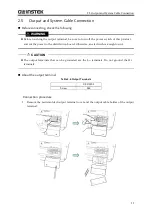
Externals, Weight, and Terminal Block

 ................................................................................ 230


9.33


Option

 ............................................................................................................................. 230


9.34


Outline Dimensional Drawing

 ........................................................................................... 231


Index

 ............................................................................................................................................... 232


Summary of Contents for GKP-2302

Page 1: ...Programmable AC DC Power Source GKP 2302 USER MANUAL GW INSTEK PART NO 82KP 23020M01 ISO 9001 CERTIFIED MANUFACTURER...

Page 2: ...er language without prior written consent of Good Will company The information in this manual was correct at the time of printing However Good Will continues to improve products and reserves the right...

Page 3: ...apters If it is the first time for you to use this product start with 1 Outline 1 Outline Explains the overview configuration and features of this product 2 Preparation before Use Explains the prepara...

Page 4: ...ound resistance is 100 or less Check the power supply voltage This product operates on the power supply voltage specified in 2 4 Grounding and Power Connections Before connecting the product to a powe...

Page 5: ...otection conductor terminal This indicates that the terminal needs to be grounded in order to prevent electric shock accidents Before operating the equipment ensure to connect this terminal to an eart...

Page 6: ...3 1 Component Name 18 3 1 1 Front 18 3 1 2 Rear 19 3 1 3 Control Panel 20 3 2 Power On Off 21 3 2 1 Before Turning on the Power 21 3 2 2 Power On 21 3 2 3 Screen Display and Operations at Starting Up...

Page 7: ...quency Setting Range Limit 53 4 1 5 About the Wattage Limiter 54 4 2 Using the Sequence Function 55 4 2 1 Basics 55 4 2 2 Sequence Function Parameters 57 4 2 3 Example of Output Using Sequence Functio...

Page 8: ...Memory 128 4 8 3 Sequence Memory 132 4 8 4 Simulation Memory 133 4 9 Using USB Memory Function 134 4 10 Using Monitor Function 135 4 11 Using Remote Sensing Function 137 4 12 Using AGC Function 139 4...

Page 9: ...80 6 REMOTE CONTROL 181 6 1 Communication Interface 182 6 1 1 USB 182 6 1 2 RS232 184 6 1 3 GPIB 186 6 2 Remote Local State Switching 188 6 2 1 Remote State 188 6 2 2 Local State 188 7 TROUBLESHOOTING...

Page 10: ...e Wave 222 9 21 Arbitrary Wave 223 9 22 External Signal Input 223 9 22 1 External Synchronous Signal Input Signal Source SYNC only 223 9 22 2 Voltage Setting Signal Input Signal Source VCA only 223 9...

Page 11: ...e 4 4 Example of Sequence 60 Figure 4 5 Process Flow in Sequence Step 61 Figure 4 6 Branch Operation Stop Operation 62 Figure 4 7 Sequence Edit View 81 Figure 4 8 Sequence Control View Output Off Stat...

Page 12: ...wn Before the Automatic Output On After the Power On 162 Figure 5 1 Component Name Display Areas on the Screen 174 Figure 5 2 Menu Composition 177 Figure 7 1 Error Message Screen Example 190 Figure 9...

Page 13: ...miter Value per Phase Reference value 54 Table 4 2 Parameters of Sequence Function 57 Table 4 3 Example of Editing Sequence 60 Table 4 4 Simulation Function Parameters 83 Table 4 5 Simulation Function...

Page 14: ...able 5 8 Menus of the Memory Function 179 Table 5 9 System Menus 180 Table 7 1 Description of the Error Message Screen 190 Table 7 2 Error Message List 193 Table 7 3 Actions When a Failure is Suspecte...

Page 15: ...1 1 OUTLINE 1 1 Overview 2 1 2 Features 2...

Page 16: ...value of the output current where the limiting value is variable You can set the limiter so that the output is turned off when the limited condition continues for a certain time Globally adjustable po...

Page 17: ...4 2 2 About Installation Environment 4 2 3 Precautions for Moving and Transportation 6 2 4 Grounding and Power Connections 7 2 5 Output and System Cable Connection 11 2 6 How to Tilt Control Panel 12...

Page 18: ...y Main unit Main Unit 1 Accessories CD ROM User Manual Programming Manual LabView Driver 1 Power Cable 3m approx 1 2 2 About Installation Environment To safely use the instrument and to maintain relia...

Page 19: ...e t h e A d j u s t e r F o o t d o w n b y u s i n g a s p a n n e r 1 9 m m d i a m e t e r D o w n Up Figure 2 1 How to Use the Adjuster Foot About arrangement Do not place the product on its side...

Page 20: ...r Moving and Transportation Follow the instructions below when moving or transporting this product Remove all wiring connected to this product Before removing the wiring be sure to turn off this produ...

Page 21: ...oduct is not grounded an electric shock might occur Ensure to connect the protective conductor terminal of the power input terminal of this product to an earth ground so that ground resistance is 100...

Page 22: ...e for a long enough time to evaporate the condensation and then connect the product to the power source Check the power source For safety use the product with the input voltage ranges and frequencies...

Page 23: ...Input Current Supplied power input cable Power Input 90 V Power Input 170 V For both 100 V and 200 V series Power Input 90 V or More Only for 200 V Series Power Input 170 V or More 3 kVA 4 50 kVA 50 A...

Page 24: ...e sure to tighten the screws firmly 3 Attach the resin molded power input terminal cover and the power input cable holder 4 Ensure that the power switch of this product is turned off and then connect...

Page 25: ...his product and cut the power to the distribution board Otherwise an electric shock might occur The output terminals that can be grounded are the Lo terminals Do not ground the Hi terminals About the...

Page 26: ...be grounded is the Lo terminals Do not ground the Hi terminal 3 Attach the resin molded terminal cover and the output cable holder 2 6 How to Tilt Control Panel You can tilt up the control panel to op...

Page 27: ...after a long period in storage This check should be performed without a load If you are not satisfied with the results of the operation check please contact GW Instek or the authorized distributor for...

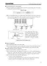
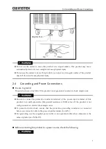
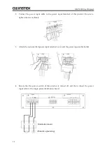
Page 28: ...GKP 2302 User Manual 14 Nothing is connected to the output terminal...

Page 29: ...and then turn off and that the GW splash screen appears on the LCD screen see 3 2 3 4 Except for a newly purchased instrument refer to 4 27 Restoring to the Factory Default Setting Reset to initialize...

Page 30: ...e AC voltage ACV is set to 0 V 7 Press the OUTPUT key to turn the output on Press the V key to open the numerical entry box for AC voltage ACV Raise the AC voltage setting value gradually by using the...

Page 31: ...17 3 BASIC OPERATION 3 1 Component Name 18 3 2 Power On Off 21 3 3 Basic Key Operations 23 3 4 Using the Continuous Function 28...

Page 32: ...USB memory port USB A port 4 9 4 Front grill The fresh air inlet An air filter is attached 8 2 5 Front grill attachment screw Screw for fixing the front grille 8 2 6 Power switch Turns the power on o...

Page 33: ...he output voltage and output current when connected to an instrument such as an oscilloscope 4 10 3 CONTROL I O connector The I O connector is used to control the instrument externally using logic sig...

Page 34: ...9 MEMORY key Displays the Memory View 4 8 10 V key Opens the numerical entry box for the output voltage setting 3 4 4 11 F key Opens the numerical entry box for the frequency setting 3 4 5 Table 3 3...

Page 35: ...10 V DC 440 V Incorrect operation may cause electric shock or result in the malfunction of your load Please check the following before starting operation When you use this product for the first time w...

Page 36: ...tartup For the Continuous function the output settings are invoked from the Basic Setting Memory No 1 and other settings are loaded from the System Setting Memory For details see 4 8 and 9 24 For the...

Page 37: ...ction when the output is on However you can move to the Memory function screen or System function screen Figure 3 5 The Root Menu 3 3 2 Item Selection You can move the cursor highlighted icon by using...

Page 38: ...hover the cursor over the box by using the arrow keys or jog and press the ENTER key This operation enables the cursor to move over each data in the data list box Hover the cursor over the item you w...

Page 39: ...jog and press the ENTER key Press the CANCEL key Press the soft key under the Close button third button from the left Figure 3 9 An Example of a Window with a Close Button Windows with an OK Cancel b...

Page 40: ...r the voltage or frequency output is applied even during the edit If you press the ENTER key or the CANCEL key the numerical entry box is closed Enter values directly by using the numeric keypad For a...

Page 41: ...aracter String Entry List Turning the jog counterclockwise Turning the jog clockwise Pressing the down arrow key Pressing the up arrow key ABCDEFGHIJKLMNOPQRSTUVWXYZabcdefghijklmnopqrstuvwxyz 01234567...

Page 42: ...re accepted 6 2 DISP Switches the measured value display mode between normal and simple 3 4 10 Ipk CLR Clears the current peak hold value 3 4 11 3 4 Using the Continuous Function 3 4 1 Setting the AC...

Page 43: ...tting cannot be set through the control panel or the remote control All conditions except for output voltage setting is same as INT SYNC The signal source is internal The frequency of the internal sig...

Page 44: ...02 User Manual 30 Operation procedures using soft keys 1 Press the Osc soft key and select 1 AC DC 2 In the displayed selection box select the desired AC DC mode 3 Press the Osc soft key and select 2...

Page 45: ...using shortcuts 1 Switching the AC DC mode Press the SHIFT key to enter the shift state the SHIFT LED illuminates When you press the 7 key of the numeric keypad during the shift state the AC DC mode i...

Page 46: ...t Range You can select the 100 V range or 200 V range Table 3 10 shows the setting range for each range Notes You cannot switch the output range in the output on state Table 3 10 The Setting Range per...

Page 47: ...cedures using the RANGE key The range is toggled between 100 V range and 200 V range every time you press the RANGE key 3 4 3 Setting Waveforms The waveforms that can be selected as the internal signa...

Page 48: ...g ACV is also switched as described above if you switch the waveform selection between SIN CLP and ARB Set ACV for SIN CLP and ARB in the output off state before you change the waveform in the output...

Page 49: ...put voltage of the internal signal source For the AC component set the output voltage in the ACV item For the DC component set it in the DCV item Notes The output voltage setting is common between SIN...

Page 50: ...ow to enter values see 3 3 5 Notes Set the RMS values for the voltages of the sine wave SIN and the clipped sine wave CLP and the Peak to Peak value for the voltage of the arbitrary waveform ARB Opera...

Page 51: ...se Set the phases when the output turns on off After the output on operation the voltage output is started from the output on phase After the output off operation the voltage output is completed when...

Page 52: ...the Simulation functions 3 4 7 Turning the Output On or Off Use the OUTPUT key to turn the output on or off The OUTPUT LED illuminates in the output on state Notes For how to turn the output on or off...

Page 53: ...ive power provided to the load The power of the phase is displayed when in the phase voltage display The total power is displayed when in the line voltage display W S Apparent power The apparent power...

Page 54: ...Vavg Iavg Ipk Hold Peak Vmax Vmin Imax Imin Ipk Hold Operation procedures using soft keys 1 Press the Measure soft key and select 2 Measure The Measure window opens 2 Select the Type item In the disp...

Page 55: ...You can switch the measured value display mode between normal Normal View and an enlarged view mode Simple View as shown in Figure 3 13 In the Simple View mode three types of measured values are disp...

Page 56: ...ed for the second item and the current peak hold value for the third Switching the measured value display mode normal simple The mode is toggled between normal and simple every time you perform the Sh...

Page 57: ...rsor over the measured value item and press the ENTER key The selection box for choosing the display items opens 3 4 11 Clearing the Output Current Peak hold Value The output current peak hold value i...

Page 58: ...n procedures using soft keys 1 Press the Measure soft key and select 2 Measure The Measure window opens 2 Move the cursor to Exec of the Ipk H Clr item and press the ENTER key 3 Close the window For h...

Page 59: ...rocedures by using shortcuts 1 Clearing the current peak hold value Press the SHIFT key to enter the shift state the SHIFT LED illuminates When you press the key in the numeric keypad in the shift sta...

Page 60: ......

Page 61: ...ction 142 4 14 Adjusting DC Offset 146 4 15 Using as DC Power Supply 147 4 16 Setting Voltage using External DC Input Signal 148 4 17 Control Using External Control Function 152 4 18 Synchronizing the...

Page 62: ...n of the peak current limiter Overvoltage protection may be avoided by lowering the limiter setting value for both negative and positive values When the number of power units that are energized is inc...

Page 63: ...e Iop Iop item set the positive negative peak current limiter value 3 Set the Output OFF item as Enable or Disable When setting to Enable also set the duration time from when the limiter is triggered...

Page 64: ...3 Notes It will take time from when the limiter starts operation to when the output current is limited enough as the RMS current limiter needs to calculate the effective value Use the peak current lim...

Page 65: ...ce can be limited Even if trying to set a voltage that exceeds the limit the setting value is restricted to the limiting value This can prevent mis setting when you do not want to set values outside t...

Page 66: ...mit that does not include an output voltage already set cannot be set In ACDC mode set the voltage setting range limit setting using the positive and negative peak values of the phase voltage regardle...

Page 67: ...cted to the limiting value This can prevent missetting when you do not want to set values outside the range The frequency setting range limiting value is common to both the 100 V and 200 V ranges For...

Page 68: ...iter value W Number of power units Per phase 1 1 5 VA 1575 2 3 VA 3150 Notes If the wattage limiter operates suppress the output wattage to within the rated output power by lowering the output voltage...

Page 69: ...eady kept is loaded The sequence setting is cleared when the power is turned off To save the setting you need to save it in internal memory or to USB memory see 4 9 Step One sequence consists of a ser...

Page 70: ...alues in the step Constant Const Fixed to the value set in the step Keep Keep Keeps the value of the current step before transitioning to the next step That is the value of the step depends on the sta...

Page 71: ...unction However harmonic current measurement see 4 4 cannot be displayed 4 2 2 Sequence Function Parameters Table 4 2 shows the parameters of the Sequence function The common parameters are common to...

Page 72: ...ets the number of times to jump to the step specified in the Jump to setting This can be set when Jump to Jump To is selected When the Jump count is set to 0 the Jump count is set to infinity Notes Th...

Page 73: ...de State output to CONTROL I O connector Code to output while the execution of the step which is specified by 2 bit H L Start Phase StartPhs Determines the phase of AC waveform of L1 phase when the st...

Page 74: ...ng Sequence Function As an example consider the sequence that gradually changes DC voltage like Figure 4 4 Set the output mode to DC INT Edit the sequence like Table 4 3 Parameters not included in thi...

Page 75: ...o 0 Start During the specified Step Time output is performed according to the Step Behavior setting When If Hold operation is executed on the way output state is kept until Resume operation is execute...

Page 76: ...ences have the default setting values when it is started next time To keep the edited contents of sequence save them in the Sequence Memory see 4 2 8 When the sequence is loaded from Sequence Memory t...

Page 77: ...the Sequence Function 63 2 Set the parameter of each step You can move between each step by changing Step No Step number 3 You can select s or ms as the unit of Step Time by selecting Misc soft key 1...

Page 78: ...y 2 Trig Out 4 2 6 Load a Sequence Notes When the sequence is loaded the sequence being edited at that time is discarded In Sequence Control View a sequence cannot be loaded Load the sequence stored i...

Page 79: ...item select 1 System 3 Specify the memory number of the sequence to be loaded in Memory No item and then push Recall soft key 4 The confirmation window for loading the sequence opens Select OK The seq...

Page 80: ...ce stored in the USB memory For how to connect USB memory to this product and how to disconnect from this product see 4 9 1 In Sequence Edit View select File soft key 2 Recall Sequence Recall View is...

Page 81: ...s Select OK The specified sequence data is loaded Notes The number of sequence data files saved in a USB memory should be 500 or less If the number of files exceeds this limit the product cannot recog...

Page 82: ...and at the same time the state transitions to step number 0 Sequence Edit View Sequence Control View Notes If an improper setting is detected during compilation an error message is displayed and the...

Page 83: ...d while sequence is executed the execution transitions to the output state that is set in the step No 0 and then sequence is terminated The output remains on Notes In the output off state the sequence...

Page 84: ...oft key while a sequence is executed the sequence is suspended The output state is kept while suspended Icon is displayed 2 To restart the sequence push Resume soft key If you push Stop soft key the e...

Page 85: ...1 or 2 that is set in the step being executed 4 2 8 Save a Sequence Notes In Sequence Control View a sequence cannot be saved All sequence data that are edited in each mode of AC DC mode are saved as...

Page 86: ...To item select 1 System 3 Specify the memory number of location to save in Memory No item and then push Store soft key 4 A window to confirm the save name opens Enter the name and then select OK For...

Page 87: ...ave a sequence to USB memory For how to connect USB memory to this product and how to disconnect from this product see 4 9 1 In Sequence Edit View select File soft key 1 Store Sequence Store View is o...

Page 88: ...list box and push Store soft key 4 A window to confirm the store name opens Enter the name and then select OK For how to enter a string see 3 3 6 Notes The number of sequence data files saved in a US...

Page 89: ...Sequence Function 75 4 2 9 Clear Rename Sequence Clear Rename a sequence saved in internal memory 1 In Sequence Edit View select File soft key 1 Store Sequence Store View is opened 2 In the To item se...

Page 90: ...3 Specify the number of memory to be operated in Memory No item 4 To clear push Clear soft key Confirmation message is displayed Select OK In the cleared number of the memory the sequence data at fac...

Page 91: ...er a new name and then select OK For how to enter a string see 3 3 6 Delete Rename a sequence saved in USB memory For how to connect USB memory to this product and how to disconnect from this product...

Page 92: ...In the To item select 2 USB 3 Select the data that is the target of the operation in the data list box 4 To clear push Delete soft key Confirmation message is displayed Select OK The corresponding fil...

Page 93: ...me and then select OK For how to enter a string see 3 3 6 4 2 10 Set so as the Sequence Function is Selected at Power on You can set so as the Sequence function is selected at power on Operation proce...

Page 94: ...4 2 12 Screen Overview The Sequence function view is broadly separated into the Sequence Edit View and the Sequence Control View It is Sequence Edit View that is displayed when sequence icon is selec...

Page 95: ...utput off state sequence stopped Measured Value to be displayed Output setting of step No 0 Icon Figure 4 8 Sequence Control View Output Off State Sequence Control View output on state sequence in exe...

Page 96: ...source independently from continuous output function Sequence function The setting is fixed to ACDC INT Keep simulation setting file The simulation setting is cleared when the power is turned off To s...

Page 97: ...epeat on off and repeat count for the simulation When the repeat is set to on and the repeat count to zero 0 the testing repeats infinitely Notes The Simulation function does not support the standard...

Page 98: ...eans that this parameter cannot be set Start phase Start Phs ON or OFF can be selected for the start phase When ON is selected the step starts at the specified start phase When OFF is selected the ste...

Page 99: ...ecified by 2 bit H L The step synchronization code can be specified also at the Initial Step Repeat Repeat You can set to repeat the simulation in a series from the Normal 1 step to the Normal 2 step...

Page 100: ...FF OFF Repeat count 2 times Voltage change simulation In this simulation the 50 Hz 100 V power source repeats the voltage change three times at 10 second intervals while the voltage drops to 70 and th...

Page 101: ...cess flow in one step The End operation causes the transition as shown in Figure 4 15 Transitions to the next step Start If the Start Phase is set to ON the output starts with the set start phase Duri...

Page 102: ...ned on from the Simulation Edit View At this point the output will be compiled and at the same time go to the initial step of the simulation see 4 3 7 Transition to Simulation Edit View Press the MENU...

Page 103: ...the parameter of each step You can move between each step by changing Step item 3 You can select s or ms as the unit of Step Time by selecting Misc soft key 1 TimeUnit 4 You can set polarity of trigg...

Page 104: ...ry default 4 3 6 Loading a Simulation Notes When a simulation is loaded the simulation you are editing is discarded Simulation cannot be loaded in the Simulation Control View Load the simulation store...

Page 105: ...n the From item select 1 System 3 Specify the memory number of simulation to be loaded in Memory No item and then push Recall soft key 4 The confirmation window for loading the simulation opens Select...

Page 106: ...n stored in the USB memory For how to connect USB memory to this product and how to disconnect from this product see 4 9 1 In Simulation Edit View select File soft key 2 Recall The Simulation Recall V...

Page 107: ...ecall soft key 5 The confirmation window for loading the simulation opens Select OK The specified simulation data is loaded Notes The number of simulation data files saved in a USB memory should be 50...

Page 108: ...ed power fluctuation is compiled and then the screen transitions to Simulation Control View Notes If an improper setting is detected during compilation an error message is displayed and the screen doe...

Page 109: ...tion is executed icon is displayed 3 When Stop soft key is pushed while simulation is executed the execution transitions to the output that is set in the Initial Step and then simulation is terminated...

Page 110: ...rned on from the Simulation Edit View The simulation will be compiled and at the same time the output will be set to the initial step of the simulation 4 3 8 Saving Simulation Notes Simulation cannot...

Page 111: ...nction 97 2 In the To item select 1 System 3 Specify the memory number of location to save in Memory No item and then push Store soft key 4 A window to confirm the save name opens Enter the name and t...

Page 112: ...in the USB memory For how to connect USB memory to this product and how to disconnect from this product see 4 9 1 In the Simulation Edit View press the select the File soft key 1 Store The Simulation...

Page 113: ...rwritten in data list box and push Store soft key 4 A window to confirm the save name opens Enter the name and then select OK For how to enter a string see 3 3 6 Notes The number of simulation data fi...

Page 114: ...4 3 9 Clear Rename Simulation Clearing renaming a simulation saved in internal memory 1 In the Simulation Edit View press the select the File soft key 1 Store The Simulation Store View opens 2 In the...

Page 115: ...n Memory No item 4 To clear push Clear soft key Confirmation message is displayed Select OK In the cleared number of the memory the simulation data at factory shipment is stored 5 To rename push Renam...

Page 116: ...on saved in USB memory For how to connect USB memory to this product and how to disconnect from this product see 4 9 1 In the Simulation Edit View press the select the File soft key 1 Store The Simula...

Page 117: ...rget of the operation in the data list box 4 To clear push Delete soft key Confirmation message is displayed Select OK The corresponding file in USB memory is deleted 5 To rename push Rename soft key...

Page 118: ...Press the MENU key to move to the root menu then select System The system setting window opens 2 In PwOn Mode item Select 3 Sim Notes To set so as to continuous output function is selected at power o...

Page 119: ...screen transitions to the Simulation Control View Notes You cannot transition to root menu by pushing the MENU key in the Simulation Control View To transition to the root menu first move to the Simu...

Page 120: ...mulation Stopped 4 4 Measuring Harmonic Current 4 4 1 Harmonic current Some electric devices of AC power input have its input current waveform greatly distorted from the sine wave When the power input...

Page 121: ...uency of 50 Hz or 60 Hz The harmonic current components up to order 40 are displayed as the RMS and a percentage to fundamental wave component Notes The Harmonic current measurement function does not...

Page 122: ...nt On an electric device using a capacitor input type rectifier circuit for power input an excessive current in comparison to the Normal state may flow for a short period of time immediately after the...

Page 123: ...d function holds either a positive or negative peak value whichever is larger in absolute value Current peak hold value is displayed in all of the Average RMS and Peak measurement views in the Normal...

Page 124: ...ut on see 3 4 6 before turning on the output The object inrush current cannot be measured correctly when the maximum peak current exceeds the one that can be supplied by this product or the peak curre...

Page 125: ...setting method differs depending on the clip depth setting method Therefore a clip ratio less than 100 makes the output voltage smaller than the setting Table 4 8 Different Output Voltage Settings De...

Page 126: ...2 User Manual 112 Operation procedure 1 In the Wave item select CLP 2 Move the cursor to Select then select it The clipped sine wave setting window opens 3 In the No item select the clipped sine wave...

Page 127: ...atio or 2 CF crest factor 5 In the CF or Clip item enter the crest factor or clip ratio 6 To save the set content into memory move the cursor to Save then press the ENTER key 7 Move the cursor to Clos...

Page 128: ...memory through the USB interface only Alternatively you can create and save the arbitrary waveform data in a USB memory and then transfer it to the internal memory of this product through this produc...

Page 129: ...rs within it 2 Connect the USB memory that has the waveform data to this product 3 Press the MEMORY key or press the MENU key to move to the root menu and then select Memory to move to the Memory View...

Page 130: ...User Manual 116 5 In the Memory No item specify the transfer destination internal memory number 6 From the data list box select the arbitrary waveform to transfer 7 Push the Copy soft key The Copy win...

Page 131: ...rary Waveform 117 8 In the Name item enter the arbitrary waveform data name Or leave it as populated which is same as the file name in the USB memory 9 Move the cursor to OK then press the ENTER key T...

Page 132: ...KP 2302 User Manual 118 4 7 5 Outputting Arbitrary Waveform Operation Method 1 In the Wave item select ARB 2 Move the cursor to Select then select it The setting window for the arbitrary waveform open...

Page 133: ...put voltage in the ACV item using Peak to Peak value Notes ACV is the setting relative to the full scale amplitude of the arbitrary waveform data When the arbitrary waveform data amplitude is not at f...

Page 134: ...operations to save these settings into the Basic Setting Memory Both the internal and USB memories can be selected as the Basic Setting Memory There are 31 internal Basic Setting Memories from No 0 to...

Page 135: ...for the data that exists on the USB memory The number of basic setting data files saved in a USB memory should be 500 or less If the number of files exceeds this limit the product cannot recognize th...

Page 136: ...ination a For the internal memory specify the destination memory number in the Memory No item then press the Store soft key b In the case of USB memory push New soft key to save for the first time To...

Page 137: ...the save name opens Enter the name and then select OK For how to enter a string see 3 3 6 Loading from a Basic Setting Memory 1 In the Memory View select Setting Recall 2 In the From item select the...

Page 138: ...ernal memory specify the memory number in the Memory No item then press the Recall soft key b For the USB memory in the data list box select the data to load then press the Recall soft key Internal me...

Page 139: ...select Setting Store 2 In the To item select the object to operate 1 System internal memory or 2 USB USB memory 3 Specify the data to operate a For the internal memory specify the memory number in th...

Page 140: ...the data to the factory default same as the one of the internal memory No 0 Erasing the basic setting data in the USB memory deletes the applicable file 5 To rename push Rename soft key Rename window...

Page 141: ...4 8 Using Memory Function 127 2 In the From item select System 3 Push the Factory soft key In the confirmation window that opens select OK The factory default basic setting data are loaded...

Page 142: ...are for triangle wave and from No 9 to No 16 for square wave Clearing an Arbitrary Waveform Memory resets its data to the factory default Inside the USB memory the GW_TOOL GW_GKP2 ARB_DATA folder is t...

Page 143: ...n the Direction item select SYS USB 3 From the data list box select the arbitrary waveform to copy 4 Push the Copy soft key A window to confirm the save name opens Enter the name Select OK to copy For...

Page 144: ...lder is overwritten No overwrite confirmation message is displayed Clearing erasing or renaming an Arbitrary Waveform Memory 1 In the Memory View select ARB Copy 2 In the Direction item select the obj...

Page 145: ...ed Select OK Clearing the internal Arbitrary Waveform Memory resets the data to triangle wave for memories from No 1 to No 8 and to square wave for memories from No 9 to No 16 Erasing an Arbitrary Wav...

Page 146: ...ing of a sequence are performed using the sequence menu see 4 2 For the content saved in the Sequence Memory see Table 4 9 The internal memory has 5 Sequence Memories from No 1 to No 5 Table 4 9 Conte...

Page 147: ...y Creation and saving of a simulation are performed using the simulation menu see 4 3 For the content saved in the Simulation Memory see Table 4 10 The internal memory has 5 Simulation Memories from N...

Page 148: ...folder of the USB memory should have folders as shown in Figure 4 23 Otherwise these folders are created automatically when the USB memory is connected to this product To remove the USB memory connec...

Page 149: ...this limit the product cannot recognize the data files in the USB memory The BACKUP and SYSTEM folders in Figure 4 23 are not used by the users Do not delete these folders and files in them as they a...

Page 150: ...tput 1 Press the MENU key to move to the root menu then select System 2 Put the cursor on Setup of the Monitor item then press the ENTER key 3 For the Type item select the output voltage or current 4...

Page 151: ...the voltage drop due to wiring to the load The Remote sensing function can be set to on in the AC INT AC VCA AC SYNC DC INT and DC VCA modes However for the AC mode it can be set to on only when the...

Page 152: ...ensing input terminal to the output voltage detecting end for example load end using a cable Turning on off Remote sensing function 1 Press the Measure soft key then select 2 Measure 2 Use the Rmt Sen...

Page 153: ...function is set to on the icon is displayed As the detected part of the output voltage calibrated by the AGC function either the sensing input terminal the Remote sensing function is on or the output...

Page 154: ...C function is forcibly set to off the settings saved in the System Setting Memory are not updated The AGC function updates the calibration factor continuously while the AGC function is on In contrast...

Page 155: ...item select 2 ON If the output voltage setting is within the AGC operation range the AGC calibration is started when ON is selected here 5 Close the window Turning off the AGC function 1 Open the AGC...

Page 156: ...this function is turned on and multiplies the gain of the output amplifier by the calculated value intending to match the output voltage with the setting value The calculated calibration factor is us...

Page 157: ...g Acal to ON becomes disabled while the Autocal function is on the ON setting of the Autocal function is retained If the difference is out of the Calibration range shown in 9 17 the Autocal function i...

Page 158: ...ion 1 Turn on the output 2 Open the AGC Autocal set window Following two methods are available a Shortcut operation b Push the Misc soft key and select 1 AGC Auto Cal 3 Use the Rmt Sense item to set t...

Page 159: ...function is calculated and the calibration is started 5 Close the window Turning off the Autocal function 1 Open the Autocal set window Following two methods are available a Shortcut operation The win...

Page 160: ...from several mV to several tens mV may exist in the output The DC offset adjustment function can reduce such DC voltage close to zero For the DC offset adjustment four types of values are retained fo...

Page 161: ...C offset gets close to zero 3 Close the window 4 15 Using as DC Power Supply You can use this product as a DC power supply by switching from the AC DC mode to the DC mode or the ACDC mode For the volt...

Page 162: ...ltage in the DCV item 4 16 Setting Voltage using External DC Input Signal In the AC VCA mode you can use the external DC input signal to set the AC output voltage of the internal signal source In the...

Page 163: ...each of AC DC modes Within the same range and the same mode the same value is retained for the gain setting value regardless of the combination of the signal sources VCA EXT ADD When the switching fro...

Page 164: ...sc soft key and select 1 AC DC From the opened menu select 1 AC 2 Press the Osc soft key and select 2 Source From the opened menu select 2 VCA 3 Set the Freq Wave and Gain items 4 Supply a DC voltage...

Page 165: ...ined for each of 100 V 200 V ranges and for each of AC DC modes Within the same range the same value is retained for the gain setting value regardless of the combination of the signal sources VCA EXT...

Page 166: ...d the starting stopping of Sequence by inputting the logic signal or the non voltage contact signal You can also get the product state by using the logic signal The polarity of state output can be swi...

Page 167: ...in I O Function Remarks 1 Output Power On Off Low Off High On 2 Output Output On Off Low On High Off negative 3 Output Protection operation Low Operate High None negative 4 Output Limiter operation Lo...

Page 168: ...his pin to anything or the product might become unstable Enabling disabling external control function 1 Press the MENU key to move to the root menu then select System The system setting window opens 2...

Page 169: ...ernal Control Function 155 Setting the polarity of the state output 1 Press the MENU key to move to the root menu then select System The system setting window opens 2 In the ExtOut Pol item select 1 N...

Page 170: ...ting the trigger output 1 Press the MENU key to move to the root menu then select System The system setting window opens 2 Move the cursor to Setup next to the Trig Out item and select it The trigger...

Page 171: ...line or the external signal The icon is displayed when the internal signal source is synchronized with the external signal The icon is displayed when the synchronization is not performed The measured...

Page 172: ...item select Line power input or Ext external input signal as the synchronization signal source 4 When the internal signal source is synchronized with the external signal or the power line the icon is...

Page 173: ...measurement function of this product Therefore the measurement operation cycle may become inappropriate depending on the external signal frequency resulting in the instable measured value display In...

Page 174: ...in the rear output terminal in the output off state when the output relay control is disabled Table 4 13 The Output Terminal Impedance Reference Values in the Rear Output Terminal in the Output Off St...

Page 175: ...Automatic Output On at Power On You can set the automatic output on after power on If you set the output on at power on setting to ON the message window as shown in Figure 4 24 is displayed for about...

Page 176: ...art up the output on at power on setting is set to off and the output is not turned on automatically The message window shown in Figure 4 24 is not displayed If the unit enters the Remote state while...

Page 177: ...product Following two measuring modes are available Instantaneous Unit kgCO2 h and Integration Unit tCO2 Users can change the coefficient for the calculation For the specification of the emission CO2...

Page 178: ...icted Rated Power You can enable or disable the energization for each power unit 1 5 kVA per unit within this product If the smaller power is needed for handling the load you can disable the energizat...

Page 179: ...d Rated Power 165 Operation procedure 1 Press the MENU key to move to the root menu then select System The system setting window opens 2 Put the cursor on the Setup next to the PU ON item then press t...

Page 180: ...d for energization If the number of the energized power units is changed the setting values of the peak current limiter and the RMS current limiter are restored to the factory default settings corresp...

Page 181: ...ng The icon is displayed when the key lock is enabled Operation procedure The Shortcut operation toggles between on off of the key lock 4 25 Beep You can set whether or not the beep sounds when perfor...

Page 182: ...r the white tone You can also adjust the contrast in 100 steps For the setting specifications see 9 23 Operation procedure 1 Open the window for adjusting the LCD Following two methods are available a...

Page 183: ...ory default setting Output on off Off Output range 100 V range AC DC mode AC mode Signal source INT External synchronization signal LINE or EXT LINE AC voltage setting 0 V Frequency 50 Hz Output wavef...

Page 184: ...Clipped sine wave Clip ratio specified Clip ratio 100 Crest factor 1 41 Arbitrary Waveform Memory ARB1 to 8 Triangle wave ARB9 to 16 Square wave Table 4 14 Setting Items to be Reset Continued Setting...

Page 185: ...sor on Exec next to the Reset item then press the ENTER key The reset operation is performed Notes If you reset the product the content in the Basic Setting Memory will not be cleared Once restarted t...

Page 186: ......

Page 187: ...173 5 DESCRIPTION OF SCREEN AND MENU 5 1 Screen Configuration 174 5 2 Menu Composition 177...

Page 188: ...displayed in the format of AC DC mode Signal source 3 4 1 d Output phase mode Current output phase mode in the system 1P2W Single phase two wire e Status icon The area where an icon is displayed when...

Page 189: ...2 Peak current limiter The peak current limiter is activated 4 1 1 Active wattage limiter The active wattage limiter is activated 4 1 5 Synchronization With SYNC the internal signal source is synchron...

Page 190: ...Maximum peak value of the output current Imin 1 Minimum peak value of the output current Ipk Hold 1 Output current peak hold value F Synchronization signal source frequency P 2 Output active power S...

Page 191: ...Remote Relay Cntrl USB Eject Trig Out PU ON Information ExtOut Pol Figure 5 2 Menu Composition 5 2 1 Menus of the Continuous Function The menus of the Continuous function are shown in Table 5 5 You ca...

Page 192: ...time unit between ms and s Trig Out Sets the trigger output File Store Saves to clears and renames the Sequence Memory Recall Recalls the Sequence Memory Clear Resets the edited sequence to the facto...

Page 193: ...played in the output on and simulation stopped states Stop Ends the simulation It is displayed in the Simulation running state Measure Makes the measured value display settings It is displayed in the...

Page 194: ...een color and the contrast 4 26 Monitor Makes the Monitor function settings 4 10 Ext Control Enables disables the external control 4 17 Remote Makes the communication interface settings 6 1 Relay Cntr...

Page 195: ...181 6 REMOTE CONTROL 6 1 Communication Interface 182 6 2 Remote Local State Switching 188...

Page 196: ...itecture VISA library If you do not have a license to use VISA library you need to obtain one generally it requires some cost The Programming Manual is included on the User Manual CD and is also downl...

Page 197: ...n Setup next to the Remote item then press the ENTER key The remote setting window opens 3 In the Interface item select USB 4 The window shows Terminator and USB ID For the USB ID see the explanation...

Page 198: ...mmunicate properly About USB ID Used for a system connected with multiple GKP 2303 programmable AC power sources through USB to enable the application identify each source The USB ID is represented in...

Page 199: ...6 1 Communication Interface 185 2 Put the cursor on Setup next to the Remote item then press the ENTER key The remote setting window opens 3 In the Interface item select RS232 4 Set each item...

Page 200: ...nt Turn off this product and the computer before connecting or disconnecting the cable Binary transmission is not supported 6 1 3 GPIB The product is compliant with the GPIB IEEE Standard 488 1 1987 T...

Page 201: ...nterface 187 2 Put the cursor on Setup next to the Remote item then press the ENTER key The remote setting window opens 3 In the Interface item select GPIB 4 In the Address item set the address Termin...

Page 202: ...ters Do not set the same address as the one used for any other device connected to the same bus Otherwise the product cannot communicate properly Binary transmission is not supported Query for the mai...

Page 203: ...189 7 TROUBLESHOOTING 7 1 Error Messages and Error Handling 190 7 2 When a Failure is Suspected 196...

Page 204: ...sage Describes the error details 7 1 5 e Press Enter Key Displayed for an error whose protection type is Output Off 7 1 2 f Soft key PU ON Displayed for an error that occurred on the power unit This k...

Page 205: ...age window press the PU ON soft key The power unit energization setting window opens 2 The power unit with an error is marked with E like Check on the power unit that has an error First leaving the en...

Page 206: ...output turns off The panel says Output OFF and Press Enter Key When you press the ENTER key you will return to the previous window for further operations if the cause of the error has been removed Ot...

Page 207: ...al frequency within the range 13 Auto Cal Disabled Message display only The Autocal setting becomes off because of out of the calibration range 15 AGC Disabled Message display only The AGC setting bec...

Page 208: ...on is connected 47 No Available Power Unit System Lock There is no power unit that can be started 48 Output Overvoltage Output Off The output voltage is excessive This may occur at an abrupt change in...

Page 209: ...RMS current limiter is activated 63 Limiting action The peak current limiter is activated The internal operation differs from that for ID 64 64 Limiting action The peak current limiter is activated Th...

Page 210: ...nt temperature may be changed from the time when the contrast was adjusted Increase the LCD contrast If the LCD display is completely invisible perform the Shortcut operation to adjust the contrast Th...

Page 211: ...ivated remove the cause see 7 1 2 Press the ENTER key to clear the error message When the message says System Locked cycle the power Output related problem The output voltage does not come up The stat...

Page 212: ...to overload Connect a load within the maximum output range or decrease the output voltage setting Excessive signal level of the signal generator When the signal source is EXT or ADD lower the level of...

Page 213: ...lue The output current overshoot occurred for the limit value While the peak current limiter is activated the overshoot may occur depending on the load 4 1 1 Remote sensing problem The Remote sensing...

Page 214: ...e is set by the communication interface The external control function is disabled in the Remote state Problem of USB memory Files in the USB memory do not appear on the screen USB eject operation was...

Page 215: ...disable the limiter to be activated or sufficiently reduce the amplitude before turning off the output 4 1 1 Memory function related problem The memory cannot be recalled The output is on The output o...

Page 216: ......

Page 217: ...203 8 MAINTENANCE 8 1 Preface 204 8 2 Daily Maintenance 204 8 3 Storage Repackaging Transportation 206 8 4 Checking Firmware Version 206...

Page 218: ...e peeled off When the front grill air filters are dirty A front grill is provided with air filters for removing dust or dirt from the intake air Clogged air filters deteriorate the ventilation resulti...

Page 219: ...ip up the control panel to its maximum angle 3 The topmost front grill is fixed at the bottom left and right to the chassis and hung at the top on the hook of the chassis Hold the front grill at the b...

Page 220: ...o falling object or dust If it may be covered with dust put the cover such as cloth and polyethylene sheet on it Avoid a place exposed to rapid temperature change or direct sunlight Store it under a n...

Page 221: ...4 Checking Firmware Version 207 2 Put the cursor on View next to the Information item then press the ENTER key 3 The Information window opens The firmware version is shown at the Firmware Version ite...

Page 222: ......

Page 223: ...18 9 14 Setting Range Limit Function 218 9 15 Remote Sensing 219 9 16 AGC 219 9 17 Autocal Output Voltage Compensation 220 9 18 Sequence 221 9 19 Simulation 221 9 20 Clipped Sine Wave 222 9 21 Arbitra...

Page 224: ...ntended output because the DC component is canceled In this case select the AC DC mode AC DC The signal source and amplification section of this product are DC coupled and the DC component is also amp...

Page 225: ...the AC DC mode SYNC Uses the internal signal source Synchronizes the frequency of the internal signal source with the signal EXT from the external synchronization signal input terminal also used as th...

Page 226: ...ine wave 3 types Output on phase 0 0 to 359 9 variable setting resolution 0 1 Output off phase 0 0 to 359 9 variable setting resolution 0 1 active inactive selectable DC offset 6 Within 20 mV typ fine...

Page 227: ...8 30 A 15 A Maximum instantaneous current 9 Peak value which is four times of the maximum current Apk Power capacity 3 kW 7 In the case of 212 V to 10 V 10 V to 212 V 424 V to 20 V 20 V to 424 V no l...

Page 228: ...to 150 V 150 V to 300 V no load reference However if the output voltage is higher than the rated value the maximum current is limited to satisfy the power capacity 12 For power input 200 V no load th...

Page 229: ...s excluding the harmonic current measurement on one screen Simple Enlarges and displays three items among all the measured values except the harmonic current measurement Voltage GKP 2303 Effective val...

Page 230: ...for a waveform of DC or sine wave Power GKP 2303 Enable W Full scale 3600 W Resolution 0 1 W 1 W 1000 W or higher Accuracy DC 45 Hz to 65 Hz 1 of rdg 1 5 W Apparent VA Full scale 4500 VA Resolution 0...

Page 231: ...of rdg 0 4 A 0 2 A 20th to 40th 1 5 of rdg 0 4 A 0 2 A Note The measurement does not conform to the IEC or other standard Display of emission CO2 GKP 2303 Displayed items Displays the instantaneous kg...

Page 232: ...range becomes half RMS current limiter GKP 2303 Setting range effective value 1 5 A to 31 5 A 1 5 A to 15 8 A Factory default 31 5 A 15 8 A Resolution 0 1 A Limiter operation Select whether to recove...

Page 233: ...the voltage used for measurement When the remote sensing is on the sensing input terminal voltage is used When it is off the output terminal voltage is used By combining with AGC or Autocal a voltage...

Page 234: ...is equal to the output voltage setting value The ratio correction factor of the detection point voltage to the output voltage setting value is used until the Autocal or the power is turned off Therefo...

Page 235: ...Jump to step Synchronous step output 2bit Specification of the branch step Trigger output Sequence control Start Stop Hold Resume Branch 1 Branch 2 Note For DC INT the AC phase voltage frequency wave...

Page 236: ...wave can be output based on the crest factor CF setting or the percent setting to the peak value GKP 2303 Number of memories 3 non volatile CF Variable range 1 10 to 1 41 Factory default 1 41 Setting...

Page 237: ...ct When synchronizing with the power input frequency no signal input is needed GKP 2303 Factory default Synchronization signal source switch External synchronization signal EXT or Power input LINE LIN...

Page 238: ...t voltage V External signal input V x Gain V V ADD Output voltage V External signal input V x Gain V V Internal signal source setting V Specification Factory default Setting Range for gain 100 V range...

Page 239: ...t etc in the non volatile Basic Setting Memory of No 1 to No 30 and recall them to use when the output is off The No 1 setting is restored at power on The No 0 setting includes the setting items for t...

Page 240: ...cks the Basic Setting Memory System Setting Memory check Checks the System Setting Memory Waveform Memory check Checks the Waveform Memory Sequence Memory check Checks the Sequence Memory Simulation M...

Page 241: ...ty reverse collective is available only for the state with Status Power On Off Low Off High On Output On Off Low On High Off Factory default negative Protection operation Low Active High None Limiter...

Page 242: ...ompliant Item Description or Selection Factory default Address 0 to 30 2 Terminator LF Note Binary transmission is not supported Note Query for the main unit status byte using a serial poll is not sup...

Page 243: ...GKP 2302 is exposed to a strong radiated radio frequency electromagnetic field or a strong radio frequency conducted disturbance Note This product may cause interference if used in residential areas S...

Page 244: ...als Weight and Terminal Block GKP 2303 Dimensions W H D 430 398 562 mm without caster wheels Weight 50 kg approx Power input terminal rear M6 screw Output terminal rear M6 screw Sensing input terminal...

Page 245: ...9 34 Outline Dimensional Drawing 231 9 34 Outline Dimensional Drawing Figure 9 2 Outline Dimensional Drawing...

Page 246: ...G 40 B Basic Setting Memory 120 179 beep 167 180 branch step 58 busy 175 C calibration 16 CANCEL key 20 21 25 caster 6 18 19 CF 39 113 176 character string entry box 27 clip ratio 111 clipped sine wav...

Page 247: ...76 Imin 39 176 Information 180 207 Initial Step 83 inrush current 108 installation environment 4 INT 29 Intra Step parameter 55 83 Ipk Hold 39 110 176 J Jog 21 Jump count 58 Jump to step 58 K Keep 56...

Page 248: ...on off 21 power switch 18 power unit energization setting22 47 164 175 191 protection type 190 PU ON 165 180 190 191 PwOn Mode 80 104 180 PwON Output 163 180 Q Q 39 176 R RANGE key 20 rated power ico...

Page 249: ...76 SVavg 176 SVmax 176 SVmin 176 SYNC 29 157 synchronization 157 175 synchronization frequency 39 System Lock 192 System menu 180 T Transition Step 83 Transition to 88 Trig Out 60 85 156 180 trigger o...

Reviews: