


x
Figure 4-23 USB Memory Folder Structure
......................................................................................... 134
Figure 4-24 The Message Window to be Shown Before the Automatic Output-On After the Power-On
Figure 5-1 Component Name (Display Areas on the Screen)
.............................................................. 174
Figure 7-1 Error Message Screen Example
......................................................................................... 190
Figure 9-1 Range of Ambient Temperature/Humidity
......................................................................... 230
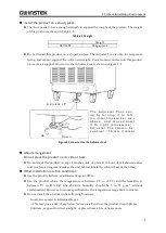
Figure 9-2 Outline Dimensional Drawing
........................................................................................... 231
Summary of Contents for GKP-2302
Page 15: ...1 1 OUTLINE 1 1 Overview 2 1 2 Features 2...
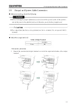
Page 28: ...GKP 2302 User Manual 14 Nothing is connected to the output terminal...
Page 60: ......
Page 186: ......
Page 187: ...173 5 DESCRIPTION OF SCREEN AND MENU 5 1 Screen Configuration 174 5 2 Menu Composition 177...
Page 195: ...181 6 REMOTE CONTROL 6 1 Communication Interface 182 6 2 Remote Local State Switching 188...
Page 216: ......
Page 222: ......


