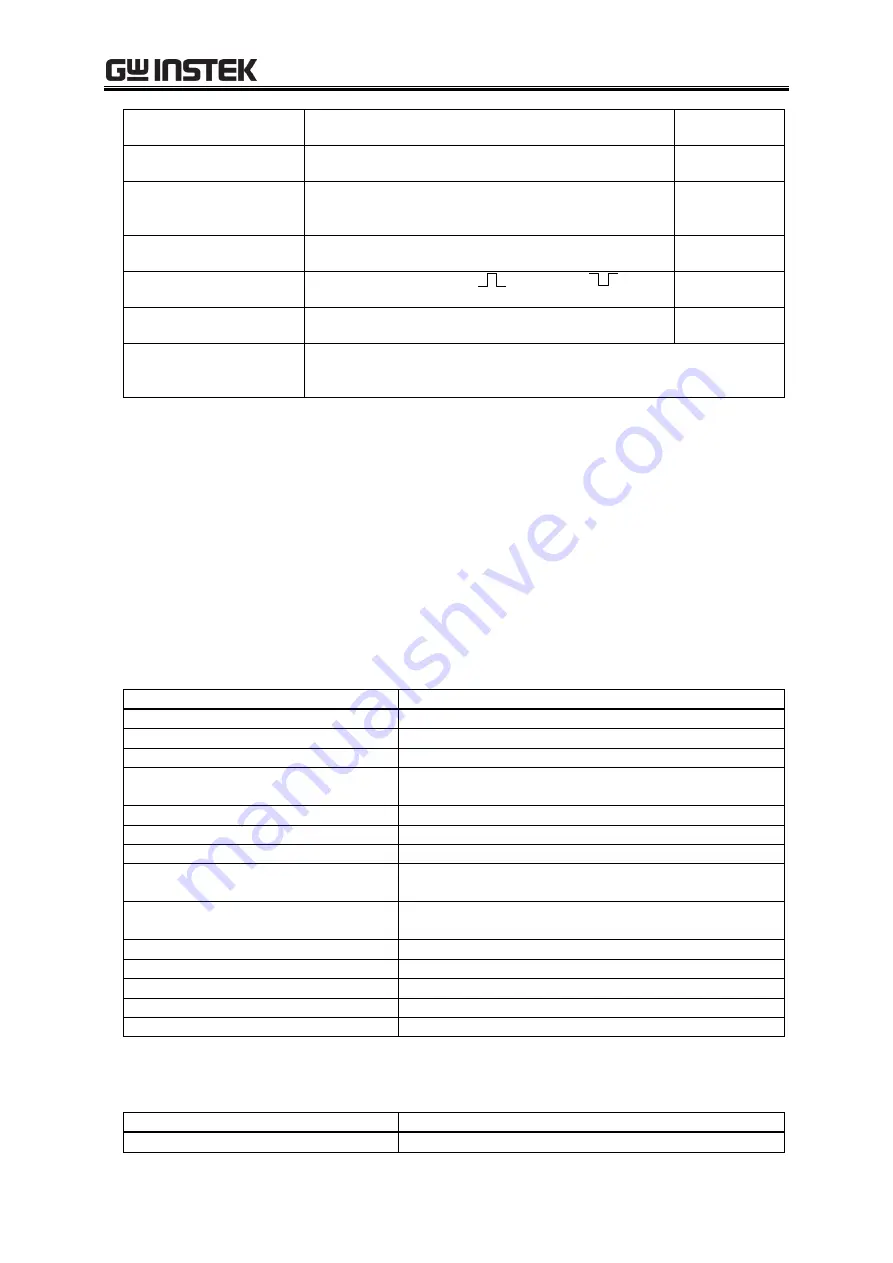
9.24 Memory Function
225
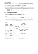
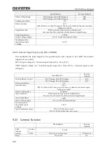
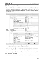
(key operation,
erroneous operation)
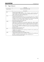
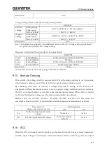
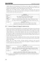
Alarms on abnormal situation regardless of the
setting
Key lock
On or Off
On: Only key lock-off and output-off are available
Off
Output relay control
On: The output relay is used to turn the output on/off
Off: The output relay is not used. High impedance to
turn the output off
On
Output setting
at power-on
On or Off
On: Output on after power-on
Off
Trigger output setting
Polarity: positive
or negative
Pulse width: 0.1 ms to 10 ms (resolution 0.1 ms)
Negative
10 ms
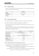
Time unit setting for
Sequence and Simulation
ms or s
s
Reset function
Resets the items stored in the System Setting Memory (excluding the
external interface setting) and the items that are to be reset at
power-on, to the factory default settings.
9.24
Memory Function
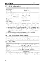
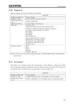
You can save basic settings (AC/DC mode, signal source, output range, AC setting, DC setting,
current limiter, setting range limit, etc.) in the non-volatile Basic Setting Memory of No.1 to
No.30, and recall them to use when the output is off. The No.1 setting is restored at power-on.
The No.0 setting includes the setting items for the factory default.
The external control, display, and other settings are saved in non-volatile System Setting
Memory when they are changed by the panel operation or remote command.
The Sequence, Simulation, clipped sine wave, and arbitrary wave are saved in their own
non-volatile memories.
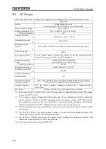
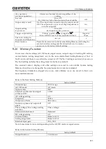
Items in the Basic Setting Memory
Factory default
Output range
100 V range
AC/DC mode
AC mode
Signal source
INT
External synchronization signal
(LINE or EXT)
LINE
AC voltage setting
0 V
Frequency
50 Hz
Output waveform
Sine wave
Output on phase and output off
phase
0.0°
Phase voltage/Line voltage setting
selection
Phase voltage
Balanced/Unbalanced
Balanced
DC voltage setting
0 V
Current limiter
Setting range limit
External input gain
100 / 200
Note: Some items do not exist depending on the AC/DC mode or signal source.
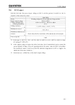
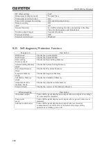
Items in the System Setting Memory
Factory default
Output function
Continuous
Summary of Contents for GKP-2302
Page 15: ...1 1 OUTLINE 1 1 Overview 2 1 2 Features 2...
Page 28: ...GKP 2302 User Manual 14 Nothing is connected to the output terminal...
Page 60: ......
Page 186: ......
Page 187: ...173 5 DESCRIPTION OF SCREEN AND MENU 5 1 Screen Configuration 174 5 2 Menu Composition 177...
Page 195: ...181 6 REMOTE CONTROL 6 1 Communication Interface 182 6 2 Remote Local State Switching 188...
Page 216: ......
Page 222: ......

