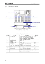
3.1 Component Name
19
3.1.2
Rear
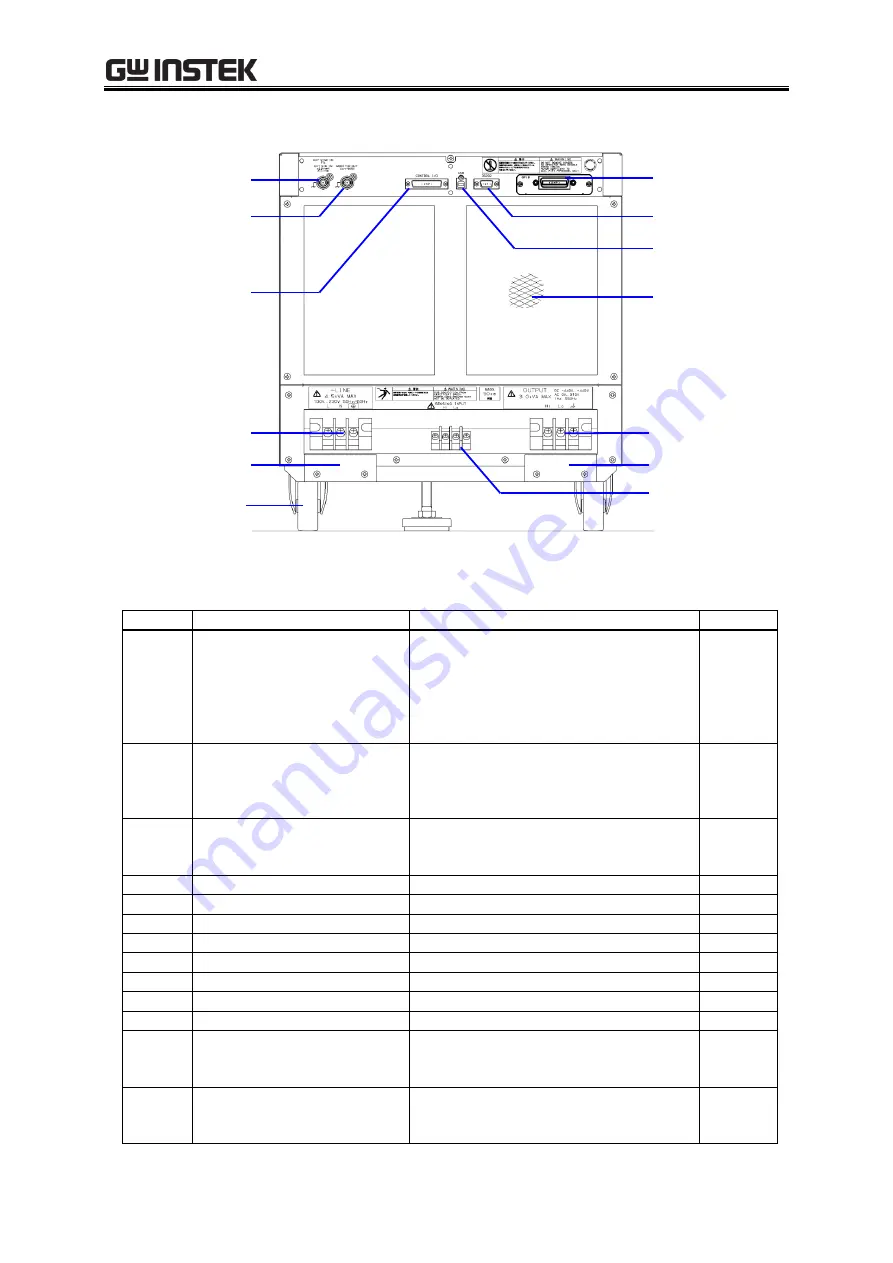
8. Power input teminal
9. Power input cable holder
10. Output teminal
11. Output cable holder
12. Sensing input teminal
1.External signal input
connector
2. Monitor output connector
3. CONTROL I/O connector
5. RS232 connector
6. USB connector
7. Air outlet
13. Caster
4. GPIB connector
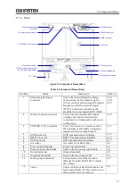
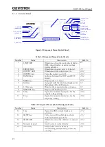
Figure 3-2 Component Name (Rear)
Table 3-2 Component Name (Rear)
Number
Name
Description
Refer to
1
External signal input
connector
Used when controlling the voltage
value setting by the external signal
(VCA), when synchronizing the output
frequency with the external signal
(SYNC), and when outputting the
amplified external signal (EXT, ADD).
2
Monitor output connector
Can be used to monitor the output
voltage and output current when
connected to an instrument such as an
oscilloscope.
3
CONTROL I/O connector
The I/O connector is used to control
the instrument externally using logic
signals and non voltage contact.
4
GPIB connector
GPIB communication interface.
5
RS232 connector
RS232 communication interface.
6
USB connector
USB communication interface.
7
Air outlet
Air outlet for exhaust heat.
8
Power input terminal
Power input terminal.
9
Power input cable holder
Used to fix the power input cable.
10
Output terminal
Output terminal.
11
Output cable holder
Used to fix the output cable.
12
Sensing input terminal
Connected to a load that is some
distance from the GKP-2303 to detect
the voltage.
13
Caster
Caster with movable front-wheels and
fixed rear-wheels. Can be used to move
this product on level surfaces.
10. Power input cable holder
Summary of Contents for GKP-2302
Page 15: ...1 1 OUTLINE 1 1 Overview 2 1 2 Features 2...
Page 28: ...GKP 2302 User Manual 14 Nothing is connected to the output terminal...
Page 60: ......
Page 186: ......
Page 187: ...173 5 DESCRIPTION OF SCREEN AND MENU 5 1 Screen Configuration 174 5 2 Menu Composition 177...
Page 195: ...181 6 REMOTE CONTROL 6 1 Communication Interface 182 6 2 Remote Local State Switching 188...
Page 216: ......
Page 222: ......

