Minimal Design for GR551x SoC
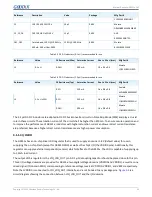
shows the pins to which the SWD interfaces connect in QFN and BGA packages.
Table 3-9 Pin matching for SWCLK and SWDIO in QFN and BGA packages
SWD
Pin # (QFN56)
Pin # (BGA68)
Pin # (BGA55)
Pin # (QFN40)
SWCLK
Pin 4
Pin C4
Pin B4
Pin 4
SWDIO
Pin 5
Pin E3
Pin B5
Pin 5
The pins can be multiplexed as GPIOs when the SWD interfaces are not in use.
3.1.6 External Flash
The GR5515I0ND SoC uses an external QSPI Flash with various model options provided. Users can choose the Flash
model on demand. When only basic operations (read, write, and erase) are required, multiple Flash models are
available.
Power consumption of Flashes in different models and from different manufacturers varies. The models with
low power consumption in Flash read stand out because that means low power consumption of GR5515I0ND.
Recommended external Flash models for GR5515I0ND are provided below:
Table 3-10 Recommended external Flash models for GR5515I0ND
Flash Model
Manufacturer
Flash Capacity
Range of Supply Power Voltage (Unit: V)
P25Q128L
Puya Semiconductor
128 Mb
1.65–2.00
P25Q128H
Puya Semiconductor
128 Mb
2.30–3.60
W25Q64JW
Winbond
64 Mb
1.70–1.95
XT25Q64D
XTX
64 Mb
1.65–2.10
W25Q64JV
Winbond
64 Mb
2.70–3.60
XM25QH64A
XMC
64 Mb
2.30–3.60
XT25F64B
XTX
64 Mb
2.70–3.60
For more details about Flash model selection for GR5515I0ND, see
GR5515I0ND Flash Selection Guide
.
Note
:
•
GR551x SDK V1.6.10 and later versions support low-voltage (1.8 V) Flash memories. Users choosing such Flash
memories should utilize GRPLT to complete eFuse configurations.
•
Flash memories vary in access speeds. For some Flash memories that cannot support data reads at 64 MHz,
decrease the QSPI communications rate according to the requirements of the specific Flash access speeds.
•
In practice, the operating frequency of GR5515I0ND Flash varies depending on component package, layout, and
routing of the whole system. Therefore, it is recommended that you choose a proper Flash memory that meets
the electrical characteristics and functional requirements based on actual project demands.
3.2 PCB Design and Layout Guideline
Copyright © 2021 Shenzhen Goodix Technology Co., Ltd.
31


