background image

13

R

EFRIGERATION

 S

YSTEM

 C

HECKS

Ensure the hold-down bolts on the compressor are secure
and have not vibrated loose during shipment. Check that vi-
bration grommets have been installed. Visually check all pip-
ing and clamps. The entire refrigeration system has been
factory charged and tested, making it unnecessary to field
charge. Factory charges are shown in Appendix C and on
the unit nameplate.

Install service manifold hoses. Gauges should read satura-
tion pressure corresponding to ambient temperature. Charge
should be checked to obtain 12° to 15° of sub-cooling per
system (i.e. compressor circuits).

S

TART

-U

P

 P

ROCEDURE


AND

 C

HECKLIST

Begin with power turned off at all disconnects.

1. Turn thermostat system switch to “Cool,” and fan

switch to “Auto” and turn temperature setting as high
as it will go.

2. Inspect all registers and set them to the normal open

position.

3. Turn on the electrical supply at the disconnect.

4. Turn the fan switch to the “ON” position. The blower

should operate after a 7-second delay.

5. Turn the fan switch to “Auto” position. The blower

should stop after a 65 second delay.

6. Slowly lower the cooling temperature until first stage

COOL (LOW COOL) starts. The blower, both fans,
and first stage compressor should now be operating.
Allow the unit to run 10 minutes, make sure cool air is
being supplied by the unit.

7. Lower the cooling temperature further until second

stage COOL (HIGH COOL) starts. The blower, both
fans, and both compressors should now be operating.
Allow the unit to run 10 minutes, make sure cool air is
being supplied by the unit.

8. Turn the temperature setting to the highest position,

stopping the unit. The indoor blower will continue to
run for 65 seconds.

9. Turn the thermostat system switch to “OFF” and

disconnect all power when servicing the unit.

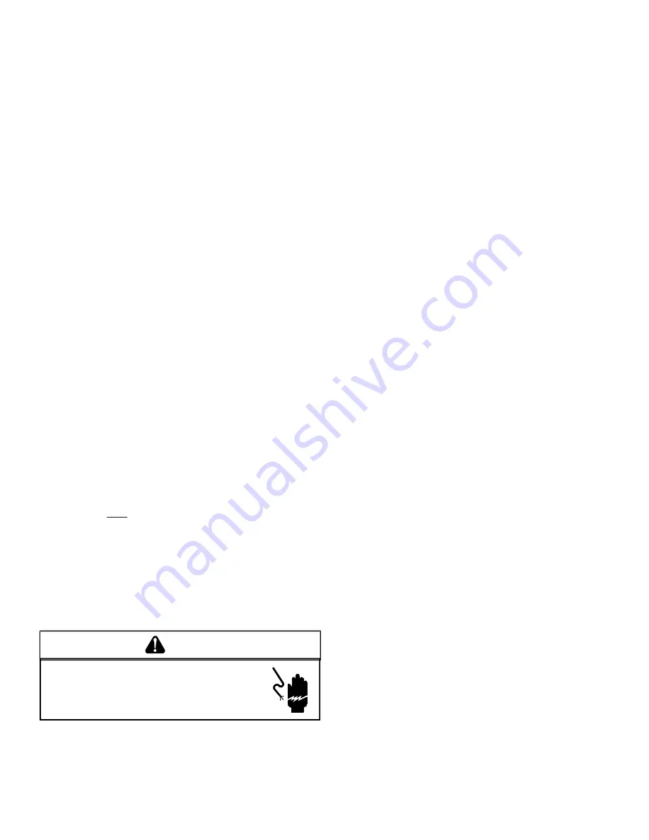
HIGH VOLTAGE! 
D

ISCONNECT


ALL


POWER


BEFORE


SERVICING


OR


INSTALLING


THIS


UNIT

. M

ULTIPLE


POWER


SOURCES


MAY


BE


PRESENT

. F

AILURE


TO


DO


SO


MAY


CAUSE


PROPERTY


DAMAGE

PERSONAL


INJURY


OR


DEATH

.

WARNING

F

INAL

 S

YSTEM

 C

HECKS

10. Check to see if all supply and return air grilles are

adjusted and the air distribution system is balanced
for the best compromise between heating and cooling.

11. Check for air leaks in the ductwork. See Sections on

Air Flow Adjustments.

12. Make sure the unit is free of “rattles”, and the tubing

in the unit is free from excessive vibration. Also make
sure tubes or lines are not rubbing against each other
or sheet metal surfaces or edges. If so, correct the
trouble.

13. Set the thermostat at the appropriate setting for

cooling and heating or automatic change over for
normal use.

14. Be sure the Owner is instructed on the unit operation,

filter, servicing, correct thermostat operation, etc.

R

EFRIGERATION

 P

ERFORMANCE

 C

HECK

Under normal summertime (full load) operating conditions,
superheat should be between 8°F and 12°F and sub-cooling
measured at the condenser outlet should be 15°F (nominal).
A 25°F to 35°F temperature difference should exist between
the entering condenser air and the temperature correspond-
ing to the compressor saturated discharge pressure. Check
that compressor RLA corresponds to values shown in Ap-
pendix C. RLA draw can be much lower than values listed at
low load conditions and low ambient condensing tempera-
tures. Values in Appendix C can slightly exceed at high load
conditions and high ambient condensing temperatures.

AIR FLOW ADJUSTMENTS

The drive on the supply fan is typically set in the middle of the
RPM range. The drive motor sheave pitch diameter is field
adjustable for the required airflow. Refer to “Drive
Adjustments” section below.

When the final adjustments are complete, the current draw
of the motor should be checked and compared to the full
load current rating of the motor. The amperage must not ex-
ceed the service factor stamped on the motor nameplate.
The total airflow must not be less than that required for op-
eration of the electric heaters or the furnace.

If an economizer is installed, check the unit operating bal-
ance with the economizer at full outside air and at minimum
outside air.  Upon completion of the air flow balancing, we
recommend replacing the variable pitched motor sheave with
a properly-sized fixed sheave. A matching fixed sheave will
provide longer belt and bearing life and vibration free opera-
tion. Initially, it is best to have a variable pitched motor sheave
for the purpose of airflow balancing, but once the balance
has been achieved, fixed sheaves maintain alignment and
minimize vibration more effectively. For direct drive units, move
green wire for fan.

NOTE: 

Never run CFM below 350 CFM per ton, evaporator

freezing or poor unit performance is possible.

Summary of Contents for 15 ton CPC Series

Page 1: ...air caution is to be observed It is your responsibility to install the product safely and to educate the customer on its safe use C US NOTE Please contact your distributor or our website for the applicable Specification Sheet referred to in this manual These installation instructions cover the outdoor installation of single package electric heating and cooling units See the Specification Sheet app...

Page 2: ...MAGE PERSONAL INJURY REDUCED UNIT PERFORMANCE AND OR HAZARDOUS CONDITIONS MAY RESULT FROM THE USE OF SUCH NON APPROVED DEVICES WARNING THIS PRODUCT CONTAINS OR PRODUCES A CHEMICAL OR CHEMICALS WHICH MAY CAUSE SERIOUS ILLNESS OR DEATH AND WHICH ARE KNOWN TO THE STATE OF CALIFORNIA TO CAUSE CANCER BIRTH DEFECTS OR OTHER REPRODUCTIVE HARM WARNING WARNING TO AVOID PROPERTY DAMAGE PERSONAL INJURY OR DE...

Page 3: ...k NY 10018 System design and installation should also where applicable follow information presented in accepted industry guides such as the ASHRAE Handbooks The manufacturer assumes no responsibility for equipment installed in violation of any code or regulation The mechanical installation of the packaged roof top units consists of making final connections between the unit and building services su...

Page 4: ...let gas vent termination or plumbing vent outlet For specific distances required consult local codes Allow minimum clearances from the enclosure for fire protection proper operation and service access see Unit Clearances These clearances must be permanently maintained When the unit is heating the temperature of the return air entering the unit must be between 50 F and 100 F GROUND LEVEL INSTALLATI...

Page 5: ...ispose of the boards and brace appropriately Curb installations must comply with local codes and should be done in accordance with the established guidelines of the National Roofing Contractors Association Proper unit installation requires that the roof curb be firmly and permanently attached to the roof structure Check for adequate fastening method prior to setting the unit on the curb Full perim...

Page 6: ...ccess and to insure proper venti lation and condenser airflow The unit must not be installed beneath any obstruction The unit should be installed re mote from all building exhausts to inhibit ingestion of exhaust air into the unit fresh air intake Insulated Panels Roof Curb Installation ROOF CURB POST INSTALLATION CHECKS After installation check the top of the curb duct connection frame and duct f...

Page 7: ... with the unit during transport Remove wood struts mounted beneath unit base frame before setting unit on roof curb These struts are intended to protect unit base frame from fork lift damage Removal is accomplished by extracting the sheet metal retainers and pulling the struts through the base of the unit Refer to rigging label on the unit Important If using bottom discharge with roof curb duct wo...

Page 8: ...ATIVE IF ASSISTANCE IS REQUIRED WARNING TO PREVENT DAMAGE TO THE WIRING PROTECT WIRING FROM SHARP EDGES FOLLOW NATIONAL ELECTRICAL CODE AND ALL LOCAL CODES AND ORDINANCES DO NOT ROUTE WIRES THROUGH REMOVABLE ACCESS PANELS CAUTION CONDUIT AND FITTINGS MUST BE WEATHER TIGHT TO PREVENT WATER ENTRY INTO THE BUILDING CAUTION For unit protection use a fuse or HACR circuit breaker that is in excess of th...

Page 9: ...D LOW VOLTAGE BLOCK LOCATIONS FAILURE OF UNIT DUE TO OPERATION ON IMPROPER LINE VOLTAGE OR WITH EXCESSIVE PHASE UNBALANCE CONSTITUTES PRODUCT ABUSE AND WILL VOID YOUR WARRANTY AND MAY CAUSE SEVERE DAMAGE TO THE UNIT ELECTRICAL COMPONENTS WARNING Areas Without Convenience Outlet It is recommended that an independent 115V power source be brought to the vicinity of the roof top unit for portable ligh...

Page 10: ...tream of the heat exchanger A cover should be tightly attached to prevent air leaks Ductwork dimensions are shown in the roof curb installation manual If desired supply and return duct connections to the unit may be made with flexible connections to reduce possible unit operating sound transmission VENTING NOTE Venting is self contained CONDENSATE DRAIN CONNECTION CONDENSATE DRAIN CONNECTION A 3 4...

Page 11: ...r Ohmmeter Test lead Minimum 16 AWG with insulated alligator clips Air temperature measuring device General refrigeration mechanics tools TEMPORARY HEATING OR COOLING If the unit is to be used for temporary heating or cooling a Startup Adjustments and Checks must first be performed in accordance with this manual Failure to comply with this requirement will void the warranty After the machines are ...

Page 12: ...life of your belt Too loose a belt will shorten its life too tight premature mo tor and bearing failure will occur Check you belt drive for adequate run in belt tension by measuring the force required to deflect the belt at the midpoint of the span length Belt tension force can be measured using a belt tension gauge available through most belt drive manufacturers t Span length inches C Center dist...

Page 13: ...ir Flow Adjustments 12 Make sure the unit is free of rattles and the tubing in the unit is free from excessive vibration Also make sure tubes or lines are not rubbing against each other or sheet metal surfaces or edges If so correct the trouble 13 Set the thermostat at the appropriate setting for cooling and heating or automatic change over for normal use 14 Be sure the Owner is instructed on the ...

Page 14: ...CAUTION Your Self Contained PackagedAir Conditioner and Heat Pump should operate for many years without excessive service calls if the unit is installed properly However it is recommended that the homeowner inspect the unit before a seasonal start up The coils should be free of debris so adequate airflow is achieved The return and supply registers should be free of any obstructions The filters sho...

Page 15: ... BY QUALI FIED SERVICE AGENCY ONLY OTHERS SHOULD NOT ATTEMPT TO SERVICE THIS EQUIPMENT Common Causes of Unsatisfactory Operation of Heat Pump on the Heating Cycle INADEQUATE AIR VOLUME THROUGH INDOOR COIL When a heat pump is in the heating cycle the indoor coil is functioning as a condenser The return air filter must always be clean and sufficient air volume must pass through the indoor coil to pr...

Page 16: ...BHP CFM BHP CFM BHP 0 2 7203 2 18 6718 1 94 0 4 7306 2 54 6777 2 14 6257 1 80 5711 1 66 0 6 7477 2 97 6899 2 51 6323 2 10 5716 1 72 5103 1 39 0 8 7112 2 96 6467 2 46 5795 2 01 5101 1 61 1 0 5983 2 38 5190 1 89 1 2 4426 1 71 CFM BHP CFM BHP CFM BHP CFM BHP CFM BHP CFM BHP CFM BHP 0 2 9664 4 05 0 4 9570 4 08 9197 3 82 8702 3 51 0 6 9038 3 82 8460 3 46 7949 3 14 0 8 8171 2 93 7630 3 70 7068 2 79 1 0 ...

Page 17: ... BHP CFM BHP CFM BHP CFM BHP CFM BHP CFM BHP CFM BHP 1 0 7120 3 26 6223 2 55 1 2 6927 3 39 5924 2 61 1 4 6739 3 52 5602 2 65 1 6 6587 3 69 5245 2 67 1 8 6419 3 84 4877 2 70 2 0 6261 4 01 CFM BHP CFM BHP CFM BHP CFM BHP CFM BHP CFM BHP CFM BHP 1 0 9090 5 79 8297 5 06 7479 3 62 1 2 8774 5 60 7914 4 83 6989 4 07 1 4 8471 5 43 7549 4 63 1 6 8209 6 14 7194 4 45 1 8 7967 6 02 6883 5 01 2 0 6594 4 87 6 C...

Page 18: ...uirements MIN MAX Qty RLA LRA Qty RLA LRA Qty HP RLA HP FLA 208 230 60 3 187 253 1 29 5 195 0 1 25 0 164 0 3 1 3 2 40 BD STD STATIC 3 0 9 2 460 60 3 414 506 1 14 7 95 0 1 12 2 100 0 3 1 3 1 20 BD STD STATIC 3 0 4 6 575 60 3 518 633 1 12 2 80 0 1 9 0 78 0 3 1 3 0 90 BD STD STATIC 3 0 4 2 MODELS 15 TON SMALLER COMPRESSOR ELECTRICAL DATA ID MOTOR APPL LARGER COMPRESSOR OD FAN MOTORS ea ID FAN MOTOR V...

Page 19: ...19 APPENDIX C UNIT DIMENSIONS VERTICAL DISCHARGE TOP VIEW 21 60 7 48 22 B C D A B C D A Model A B C D 15 Ton 20 Ton 133 1 2 88 7 32 50 9 32 5 5 32 ...

Page 20: ...20 2010 Goodman Manufacturing Company L P 5151 San Felipe Suite 500 Houston TX 77056 www goodmanmfg com www amana hac com ...

Reviews: