SERVICING
50
7. As the unit fires, the inclined manometer negative pressure
will drop to -1.0" ± 0.1" W.C.
8. If not as listed, replace control.
Note:
The pressure switch
must
be mounted with the diaphragm
in a vertical position.
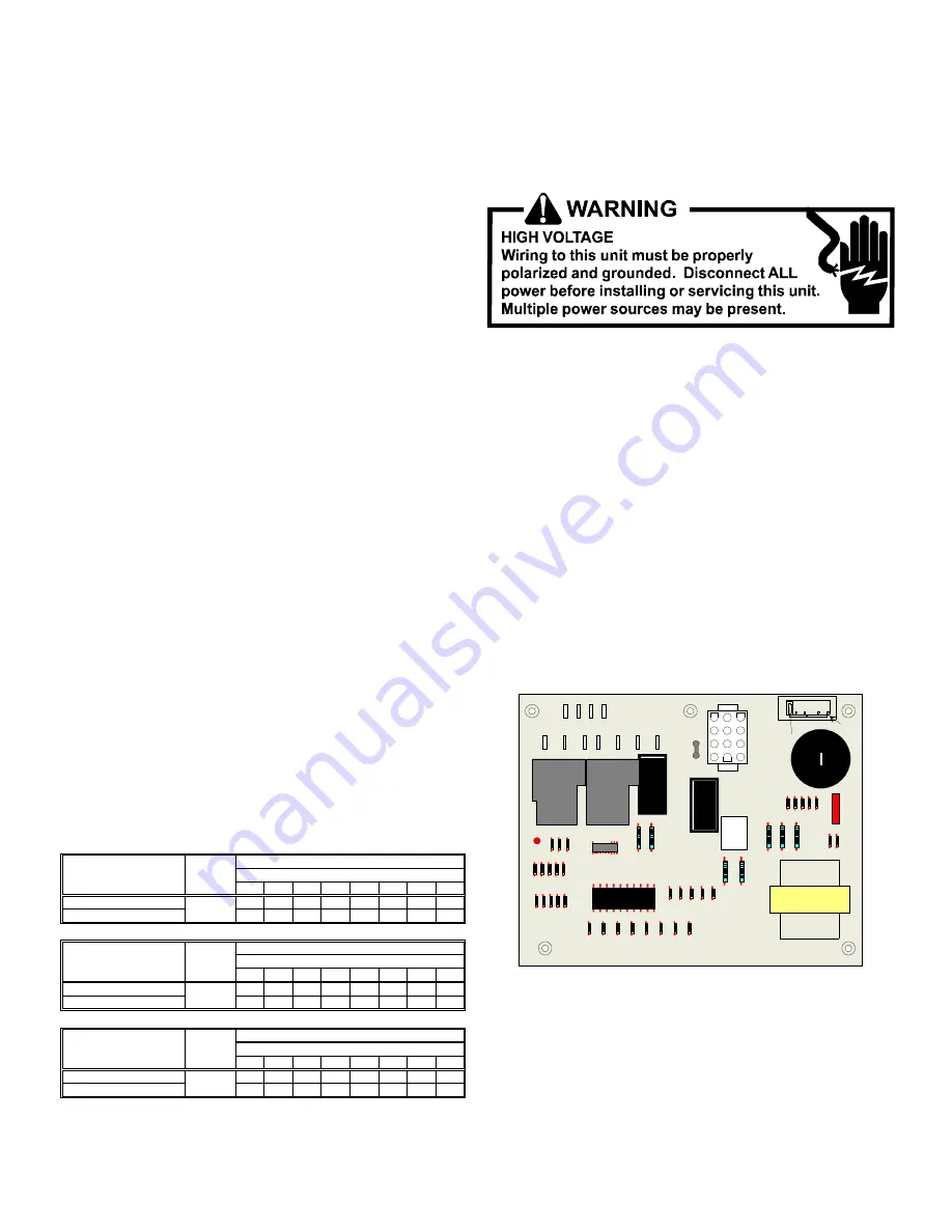
S-311 HIGH ALTITUDE APPLICATION
High Altitude Derate - U.S. Installations Only (Optional)
High Altitude Derate is not required for proper operation. The
gas/electric units naturally derate with altitude. High Altitude
Derate kit may be installed if desired.
IMPORTANT NOTE:
The gas/electric units naturally derate
with altitude. Do not attempt to increase the firing rate by
changing orifices or increasing the manifold pressure. This
can cause poor combustion and equipment failure. At all
altitudes, the manifold pressure must be within 0.3 inches
W.C. of that listed on the nameplate for the fuel used. At all
altitudes and with either fuel, the air temperature rise must be
within the range listed on the unit nameplate. Refer to the
Installation Manual provided with the LP kit for conversion from
natural gas to propane gas and for altitude adjustments.
When this package unit is installed at high altitude, the appro-
priate High Altitude orifice kit may be installed. As altitude
increases, there is a natural reduction in the density of both
the gas fuel and combustion air. This kit will provide the proper
design certified input rate within the specified altitude range.
High altitude kits are not approved for use in Canada. For in-
stallations above 2,000 feet, use kit HA-02. The HA-02 kit is
used for both Natural and LP gas at high altitudes.
Use LPT-00A propane conversion kit for propane conversions
at altitudes below 2000 feet. Natural gas installations below
2000 feet do not require a kit.
For propane conversion above 2000 feet, high altitude kit HA-
02 is required in addition to the LPT-00A propane conversion
kit.
Natural gas and LP gas installations at altitudes > 2000 ft
2000
3000
4000
4500
5000
6000
7000
8000
U.S. BURNER ORIFICE
45/55 47/55 47/56
-
47/56 48/57 48/58 49/58
CANADA BURNER ORIFICE
45/55
-
-
48/57
-
-
-
-
2000
3000
4000
4500
5000
6000
7000
8000
U.S. BURNER ORIFICE
44/55 44/55 45/56
-
45/56 46/57 47/58 47/58
CANADA BURNER ORIFICE
44/55
-
-
47/57
-
-
-
-
2000
3000
4000
4500
5000
6000
7000
8000
U.S. BURNER ORIFICE
43/55 53/55 44/56
-
44/56 44/56 45/57 45/57
CANADA BURNER ORIFICE
43/55
-
-
46/57
-
-
-
-
ELEVATION ABOVE SEA-LEVEL (FEET)
20,000 BTUH NAT/20,OOO BTUH/L.P.
INPUT/BURNER
INPUT/BURNER
HIGH
ALTITUDE
KIT
HA02
HIGH
ALTITUDE
KIT
22,500 BTUH NAT/20,OOO BTUH/L.P.
ELEVATION ABOVE SEA-LEVEL (FEET)
HA02
HA02
INPUT/BURNER
25,000 BTUH NAT/20,OOO BTUH/L.P.
ELEVATION ABOVE SEA-LEVEL (FEET)
HIGH
ALTITUDE
KIT
S-313 TESTING IGNITION CONTROL MODULE
NOTE:
Failure to earth ground the unit, reversing the neutral
and hot wire connection to the line (polarity), or a high resis-
tance connection in the ground or neutral lines may cause the
control to lockout due to failure to detect flame.
The ground wire must run from the unit all the way back to the
electrical panel. Proper grounding can be confirmed by dis-
connecting the electrical power and measuring resistance be-
tween the neutral (white) connection and the burner closest to
the flame sensor. Resistance should be less than 10 ohms.
DSI Direct Spark Ignition Systems
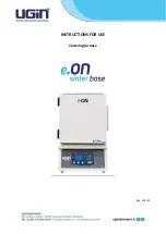
NORMAL SEQUENCE OF OPERATION (DSI Direct Spark
Ignition System)
1. Thermostat calls for heat by energizing "W". The control
checks the pressure switch for open condition. If the pres-
sure switch is closed the control will flash code "3" and
wait for the pressure switch to open.
2. The induced draft motor is energized and the control flashes
code "2" and waits for the pressure switch to close. Once
the pressure switch is closed, the LED stops flashing and
the control begins timing the 15 second pre-purge.
3
2
1
6
5
4
9
8
7
12
11
10
L2
L2
L2
L2
COOL
HEAT
UNUSED
L1
L1
D1
FS
D
iag
n
o
st
ic
L
E
D
Blower Off Delay Settings
Transformer
speed up
DSI Control Board
3. The control energizes the spark igniter and gas valve for 7
seconds. If flame is established, the control goes into a 30
second heat on delay.
4. The indoor blower is energized at the heat speed after a 30
second on delay.
5. The control monitors the safety circuit inputs, flame, and
thermostat during operation.

![Preview for 36 page of Goodman [A/G]PG Service Instructions Manual](http://thumbs.mh-extra.com/thumbs/goodman/a-g-pg/a-g-pg_service-instructions-manual_2243406-36.webp)
![Preview for 37 page of Goodman [A/G]PG Service Instructions Manual](http://thumbs.mh-extra.com/thumbs/goodman/a-g-pg/a-g-pg_service-instructions-manual_2243406-37.webp)
![Preview for 38 page of Goodman [A/G]PG Service Instructions Manual](http://thumbs.mh-extra.com/thumbs/goodman/a-g-pg/a-g-pg_service-instructions-manual_2243406-38.webp)
![Preview for 39 page of Goodman [A/G]PG Service Instructions Manual](http://thumbs.mh-extra.com/thumbs/goodman/a-g-pg/a-g-pg_service-instructions-manual_2243406-39.webp)
![Preview for 40 page of Goodman [A/G]PG Service Instructions Manual](http://thumbs.mh-extra.com/thumbs/goodman/a-g-pg/a-g-pg_service-instructions-manual_2243406-40.webp)
![Preview for 41 page of Goodman [A/G]PG Service Instructions Manual](http://thumbs.mh-extra.com/thumbs/goodman/a-g-pg/a-g-pg_service-instructions-manual_2243406-41.webp)
![Preview for 42 page of Goodman [A/G]PG Service Instructions Manual](http://thumbs.mh-extra.com/thumbs/goodman/a-g-pg/a-g-pg_service-instructions-manual_2243406-42.webp)
![Preview for 43 page of Goodman [A/G]PG Service Instructions Manual](http://thumbs.mh-extra.com/thumbs/goodman/a-g-pg/a-g-pg_service-instructions-manual_2243406-43.webp)
![Preview for 44 page of Goodman [A/G]PG Service Instructions Manual](http://thumbs.mh-extra.com/thumbs/goodman/a-g-pg/a-g-pg_service-instructions-manual_2243406-44.webp)
![Preview for 45 page of Goodman [A/G]PG Service Instructions Manual](http://thumbs.mh-extra.com/thumbs/goodman/a-g-pg/a-g-pg_service-instructions-manual_2243406-45.webp)
![Preview for 46 page of Goodman [A/G]PG Service Instructions Manual](http://thumbs.mh-extra.com/thumbs/goodman/a-g-pg/a-g-pg_service-instructions-manual_2243406-46.webp)
![Preview for 47 page of Goodman [A/G]PG Service Instructions Manual](http://thumbs.mh-extra.com/thumbs/goodman/a-g-pg/a-g-pg_service-instructions-manual_2243406-47.webp)
![Preview for 48 page of Goodman [A/G]PG Service Instructions Manual](http://thumbs.mh-extra.com/thumbs/goodman/a-g-pg/a-g-pg_service-instructions-manual_2243406-48.webp)
![Preview for 49 page of Goodman [A/G]PG Service Instructions Manual](http://thumbs.mh-extra.com/thumbs/goodman/a-g-pg/a-g-pg_service-instructions-manual_2243406-49.webp)
![Preview for 50 page of Goodman [A/G]PG Service Instructions Manual](http://thumbs.mh-extra.com/thumbs/goodman/a-g-pg/a-g-pg_service-instructions-manual_2243406-50.webp)
![Preview for 51 page of Goodman [A/G]PG Service Instructions Manual](http://thumbs.mh-extra.com/thumbs/goodman/a-g-pg/a-g-pg_service-instructions-manual_2243406-51.webp)
![Preview for 52 page of Goodman [A/G]PG Service Instructions Manual](http://thumbs.mh-extra.com/thumbs/goodman/a-g-pg/a-g-pg_service-instructions-manual_2243406-52.webp)


