background image

Refer to Service Manual RS6200006 for installation, operation & troubleshooting information.

All safety information must be followed as provided in the Service Manual.

Refer to the appropriate Parts Catalog for part number information.

Models listed on page 3.

TECHNICAL MANU

TECHNICAL MANU

TECHNICAL MANU

TECHNICAL MANU

TECHNICAL MANUAL

AL

AL

AL

AL

RT6121001r2

January 2011

Copyright © 2010 - 2011 Goo

dman Manufacturing Company, L.P.

This manual is to be used by qualified, professionally trained HVAC technicians only. Goodman
does not assume any responsibility for property damage or personal injury due to improper
service procedures or services performed by an unqualified person.

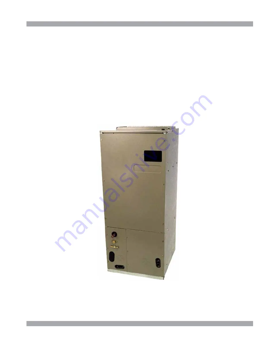
AVPTC Air Handlers


Summary of Contents for AVPTC AVPTC183014

Page 1: ...d on page 3 TECHNICAL MANU TECHNICAL MANU TECHNICAL MANU TECHNICAL MANU TECHNICAL MANUAL AL AL AL AL RT6121001r2 January2011 Copyright 2010 2011 Goodman Manufacturing Company L P This manual is to be used by qualified professionally trained HVAC technicians only Goodman does not assume any responsibility for property damage or personal injury due to improper service procedures or services performe...

Page 2: ...rom improper service or service procedures If you install or perform service on this unit you assume responsibility for any personal injury or property damage which may result Many jurisdictions require a license to install or service heating and air conditioning equipment WARNING WARNING WARNING WARNING All Airhandlers use DIRECT DRIVE MOTORS Power supply is AC 208 230v 60 hz 1 phase A V P T C 18...

Page 3: ...he environment and can lead to the imposition of substantial fines These regulations may vary by jurisdiction Should questions arise contact your local EPA office WARNING WARNING Do not connect or use any device that is not design certified by Goodman for use with this unit Serious property damage personal injury reduced unit performance and or hazardous conditions may result from the use of such ...

Page 4: ...PPLY IS 220 240 V 60 HZ 1 PHASE Installation Before installing this appliance insure that it is properly sized and adequate power is available This appliance can be installed in the vertical position with out modification The horizontal left and downflow positions require product modification and instructions for these field conversions can be found in the AVPTC installation instruction manual Thi...

Page 5: ...OTE The DPIH insu lation kit is not supplied with this product and must be purchasedseparately See following chart for the correct DPIH kit AVPTC Model Insulation Kit 1830 DPIH36 42 3137 4260 DPIH48 61 AVPTC is a multi position variable speed air handler and is used with R 410A The unit s blower design includes a vari able speed ECM motor and is compatible with heat pumps and variable capacity coo...

Page 6: ... 2 19 1 2 10 14 1 2 11 15 16 17 1 8 17 15 16 2 AVPTC313714 53 1 4 24 20 22 12 19 5 8 11 15 16 19 5 8 19 15 16 1 13 16 AVPTC426014 53 1 4 24 20 22 12 19 5 8 11 15 16 19 5 8 19 15 16 1 13 16 A B E SUCTION LINE LIQUID LINE INLET TUBE I INLET RIGHT SIDE VIEW H INLET FRONT VIEW D C F G ...

Page 7: ...tion Size Coil Drain Connection FPT 3 4 3 4 3 4 Liquid 3 8 3 8 3 8 Suction 3 4 7 8 7 8 Electrical Data Voltage 208 240 208 240 208 240 Min Circuit Ampacity 4 9 4 9 6 5 6 5 8 6 8 6 Max Overcurrent Device amps 15 15 15 15 15 15 Minimum VAC 197 197 197 Maximum VAC 253 253 253 Blower Motor FLA 3 90 5 20 6 90 HP 1 2 3 4 1 Ship Weight lbs 127 178 197 ...

Page 8: ... 30 sec 50 To set airflow 1 Select model and desired To set airflow 1 Select model and desired 1 Select model and desired high stage cooling airflow Determine the cooresponding tap high stage cooling airflow Determine the cooresponding tap A B C or D Set dip switches 1 and 2 to the appropriate ON OFF positions 2 Select model and installed electric A 810 1210 C 1047 1562 D 1209 1804 A 409 610 B 553...

Page 9: ... ON OFF OFF OFF 5 0 5 OFF ON ON ON ON 0 0 0 ON OFF ON ON ON 5 5 0 OFF OFF ON or OFF ON or OFF ON or OFF 0 0 0 BIAS Dipswitches Indoor Control TERM1 TERM2 Termination dipswitches at outdoor unit See installation instructions with CT TM compatiable outdoor unit Data Line Voltages Vdc Outdoor Control 1 C 2 C 1 2 TERM Dipswitches 1 2 ON OFF 3 BIAS BIAS TERM Indoor Unit BIAS and TERMINATION Dipswitches...

Page 10: ... GREEN RX LED INDICATES NETWORK TRAFFIC USE LEARN BUTTON TO RESET NETWORK BIAS BK 3 HI VOLTAGE 230V 3 IF ANY OF THE ORIGINAL WIRES AS SUPPLIED WITH THIS UNIT MUST BE REPLACED IT MUST BE REPLACED WITH WIRING MATERIAL HAVING A TEMPERATURE RATING OF AT LEAST 105 C USE COPPER CONDUCTORS ONLY RX LED 4 24V THERMOSTAT CONNECTIONS 7 DISCARD CONNECTOR PL1 WHEN INSTALLING OPTIONAL HEAT KIT 1 PLACE RED WIRE ...

Reviews: