40
•
Drainage system. Check for blockage and/or leakage. Check hose connections at and internal to furnace.
•
Wiring. Check electrical connections for tightness and/or corrosion. Check wires for damage.
•
Filters.
F
ILTERS
F
ILTER
M
AINTENANCE
Improper filter maintenance is the most com-
mon cause of inadequate heating or cooling
performance. Filters should be cleaned (per-
manent) or replaced (disposable) every two
months or as required. When replacing a fil-
ter, it must be replaced with a filter of the
same type and size.
F
ILTER
R
EMOVAL
Depending on the installation, differing filter
arrangements can be applied. Filters can be
installed in either the central return register
or a side panel external filter rack (upflow only).
A media air filter or electronic air cleaner can
be used as an alternate filter. Follow the filter
sizes given in the Recommended Minimum Fil-
ter size table to ensure proper unit perfor-
mance.
To remove filters from an external filter rack in an upright upflow installation, follow the directions provided with external filter rack
kit.
H
ORIZONTAL
U
NIT
F
ILTER
R
EMOVAL
Filters in horizontal installations are located in the central return register or the ductwork near the furnace.
To remove:
1. Turn OFF electrical power to furnace.
2. Remove filter(s) from the central return register or ductwork.
3. Replace filter(s) by reversing the procedure for removal.
4. Turn ON electrical power to furnace.
M
EDIA
A
IR
F
ILTER
OR
E
LECTRONIC
A
IR
C
LEANER
R
EMOVAL
Follow the manufacturer’s directions for service.
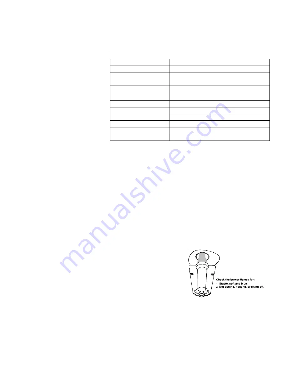
B
URNERS
Visually inspect the burner flames periodically during the heating season. Turn on the
furnace at the thermostat and allow several minutes for flames to stabilize, since any
dislodged dust will alter the flames normal appearance. Flames should be stable, quiet,
soft, and blue (dust may cause orange tips but they must not be yellow). They should
extend directly outward from the burners without curling, floating, or lifting off. Flames
must not impinge on the sides of the heat exchanger firing tubes.
Burner Flame
Figure 43
DIAGNOSTIC CODES
1 flash, then pause
System lockout
2 flashes, then pause
Pressure switch stuck closed
3 flashes, then pause
Pressure switch stuck open
4 flashes, then pause
Open limit switch
5 flashes, then pause
Flame has been sensed when no flame
should be present (no call for heat)
6 flashes, then pause
Open rollout switch / open control board fuse
7 flashes, then pause
Low flame sense signal
8 flashes, then pause
Igniter relay fault
Continuous flashing
115 Volt AC power reversed
OFF
Control failure
ON
Normal operation
The LED will also flash once at power-up.


