background image

2

www.goodmanmfg.com

SS-GCEC96

SS-GCEC96

www.goodmanmfg.com

3

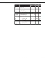
Product Specifications

GCEC96

0403BNA

 GCEC96

0603BNA 

 GCEC96

0803BNA 

GCEC96

1005CNA

Heating Data

High Fire Input¹

40,000

60,000

80,000

100,000

High Fire Output¹

38,400

57,600

76,800

96,000

Low-Fire Input¹

28,000

42,000

56,000

70,000

Low-Fire Output¹

26,880

40,320

53,760

67,200

AFUE²

96

96

96

96

Temp. Rise Range (°F)

20 - 50

20 - 50

35 - 65

35 - 65

Vent Diameter³

2" - 3"

2" - 3"

2" - 3"

2" - 3"

No. of Burners

2

3

4

5

Circulator Blower

Available AC @ 0.5" ESP

1.5 - 3

1.5 - 3

1.5 - 3

3 -  5

Size  (D x W)

10" x 8"

11" x 8"

11" x 8"

11" x 10"

Horsepower @ 1075 RPM

 1/2

 1/2

 1/2

1

Speed

5

5

5

5

Electrical Data

Min. Circuit Ampacity⁴

8

8

8

13.3

Max. Overcurrent (amps)⁵

15

15

15

15

Shipping Weight (lbs)

112

115

118

140

¹ 

Natural Gas BTU/h

²  DOE AFUE based upon Isolated Combustion System (ICS)
³  Installer must supply one or two PVC pipes: one for combustion air (optional) and one for the flue outlet (required). Vent pipe must be either 2” or 3” in diameter, depending upon 

furnace input, number of elbows, length of run and installation (1 or 2 pipes). The optional Combustion Air Pipe is dependent on installation/code requirements and must be 2” or 

3” diameter PVC.

⁴ 

Minimum Circuit Ampacity = (1.25 x Circulator Blower Amps) + ID Blower amps. Wire size should be determined in accordance with National Electrical Codes. Extensive wire runs 

will require larger wire sizes.

⁵  Maximum Overcurrent Protection Device refers to maximum recommended fuse or circuit breaker size. May use fuses or HACR-type circuit breakers of the same size as noted.

Notes

• 

All furnaces are manufactured for use on 115 VAC, 60 Hz, single-phase electrical supply.

• 

Gas Service Connection ½” FPT

• 

Important: Size fuses and wires properly and make electrical connections in accordance with the National Electrical Code and/or all existing local codes.

• 

For bottom return: Failure to unfold flanges may reduce airflow by up to 18%. This could result in performance and noise issues.

• 

For servicing or cleaning, a 24” front clearance is required. Unit connections (electrical, flue and drain) may necessitate greater clearances than the minimum clearances listed 

above. In all cases, accessibility clearance must take precedence over clearances from the enclosure where accessibility clearances are greater.

Summary of Contents for GCEC96

Page 1: ...down flow horizontal left or right Certified for direct vent 2 pipe or non direct vent 1 pipe Easy to install top venting with optional side venting Convenient left or right connection for gas and ele...

Page 2: ...ontrol Configuration NOx M Upflow Horizontal N Low NOx C Downflow Horizontal Cabinet Width Motor B 17 C 21 V Variable Speed ECM ComfortNet D 24 E Multi Speed ECM S Single Speed Maximum CFM 2 800 CFM 4...

Page 3: ...ipes The optional Combustion Air Pipe is dependent on installation code requirements and must be 2 or 3 diameter PVC Minimum Circuit Ampacity 1 25 x Circulator Blower Amps ID Blower amps Wire size sho...

Page 4: ...ernate Gas High Voltage Electrical Outlet Standard Drain Trap Drain Trap Holes Alternate Gas Supply Alternate Vent High Voltage Electrical Outlet Right Side Exterior Drain Trap Holes Low Voltage Elect...

Page 5: ...78 1035 1002 964 ON ON ON Ylo 939 894 846 806 759 706 661 614 Y 1137 1096 1056 1018 981 940 897 859 CONTINUOUS FAN Dipswitch Setting S2 2 S2 3 S2 4 Static 0 1 0 2 0 3 0 4 0 5 0 6 0 7 0 8 Tstat Call CF...

Page 6: ...969 928 ON ON ON Ylo 1328 1287 1249 1215 1170 1131 1085 1046 Y 782 629 547 469 396 333 N A N A CONTINUOUS FAN Dipswitch Setting S2 2 S2 3 S2 4 Static 0 1 0 2 0 3 0 4 0 5 0 6 0 7 0 8 Tstat Call CFM CF...

Page 7: ...Ylo 1311 1293 1249 1203 1172 1122 1088 1041 Y 750 644 569 507 442 388 328 N A CONTINUOUS FAN Dipswitch Setting S2 2 S2 3 S2 4 Static 0 1 0 2 0 3 0 4 0 5 0 6 0 7 0 8 Tstat Call CFM CFM CFM CFM CFM CFM...

Page 8: ...73 ON ON ON Ylo 1866 1817 1774 1729 1684 1637 1593 1552 Y 1477 1422 1364 1301 1244 1190 1135 1078 CONTINUOUS FAN Dipswitch Setting S2 2 S2 3 S2 4 Static 0 1 0 2 0 3 0 4 0 5 0 6 0 7 0 8 Tstat Call CFM...

Page 9: ...BTU HR x 1000 BTU OUTPUT vs TEMPERATURE RISE CHART TEMPERATURE RISE 600 CFM 700 900 1000 1100 1200 1400 1600 1800 2000 2200 2400 CFM FORMULAS BTU OUTPUT CFM x 1 08 x RISE RISE BTU OUTPUT 1 08 CFM 800...

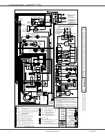
Page 10: ...GND INTERNAL TO SWITCH PRESSURE HIGH FIRE PROT DEVICE INTEGRATED CONTROL PK PU PLUG CONNECTION L N BK C DOOR OPEN OPEN WHEN DOOR SWITCH COMPARTMENT BLOWER SWITCH TEMP GND 1 BLOWER CIRCULATOR JUNCTION...

Page 11: ...5 CFSB21 Downflow Sub Base 21 RF000142 Drain Kit Horizontal Left Vertical Flue 0170K00000S Flush Mount Vent Kit 3 or 2 0170K00001S Flush Mount Vent Kit 2 AFE18 60A Fossil Fuel Dual Fuel Kit HASFK Hig...

Page 12: ...EC96 Goodman Manufacturing Company L P reserves the right to discontinue or change at any time specifications or designs without notice or without incurring obligations 2021 Goodman Manufacturing Comp...

Reviews: