IO-231
6/03
7
THE VENT AND COMBUSTION AIR SUPPLY PIPES
MUST BE INSPECTED ANNUALLY.
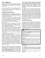
Visually check the vent terminal and combustion air supply
pipe screens, clean if necessary. Visually check for
blockage of the condensate disposal system. Hoses may
be disconnected to determine that proper flow is
maintained. Should an obstruction be observed, it can be
dislodged by forcing a stream of water through it using a
device such as a garden hose.
Materials and procedures must conform to the ASTM
Standards.
Pipe and Fittings ASTM 1785, D2465 and D2266
PVC Primer and Solvent Cement ASTM D2564
Procedure for Cementing Joints ASTM D2855 (ref.) This
appliance may be vertically or horizontally vented.
HORIZONTAL THROUGH THE WALL
VENTING
This appliance may be horizontally vented through an
exterior wall following the applicable instructions in the
“VENTING” section in conjunction with these additional
requirements.
ALL HORIZONTAL VENT INSTALLATIONS MUST BE
MADE IN ACCORDANCE WITH THESE
INSTRUCTIONS.
When selecting which exterior wall to penetrate, the
following items should be taken into consideration:
1. Layout the combustion air and vent system to avoid
the possibility of interference with beams, poles, posts,
electrical wiring, plumbing, etc.
2. When possible the combustion air and vent
termination should not be subjected to prevailing
winds.
3. The combustion air intake and vent termination must
be located at least twelve (12) inches above expected
snowfall. Consideration should be made to past
unusual snowfalls.
•
DO NOT
locate the terminal less than seven (7)
feet above public walkways. This applies to steps
and stairwells.
•
DO NOT
locate the termination areas where
condensate may present a problem such as
flowerbeds, patios, etc.
•
DO NOT
locate within four (4) feet of a gas meter,
electric meter, or gas regulator; (3) feet in Canada
•
DO NOT
locate the vent terminal within four (4)
feet of an adjacent building.
•
DIRECT VENT INSTALLATION - DO NOT
locate
the vent terminal within twelve (12) inches of an
operable window or door.
•
NON-DIRECT VENT INSTALLATION - DO NOT
locate the vent terminal less than (12) inches
above a door or operable window.
•
NON-DIRECT VENT INSTALLATION - DO NOT
locate the vent terminal less than (4) feet below or
(4) feet horizontally from any door, window or gravity
air inlet into any building.
•
DO NOT
locate the vent terminal less than three
(3) feet above, or (10) feet horizontally from, a
forced air inlet into any building, other than the
combustion air supply pipe.
•
DO NOT
locate the vent terminal within three (3)
feet of an inside corner of a building or structure.
Minor corners created by fireplace chimneys are
excluded from this requirement.
To protect the exterior surface from staining due to the
condensate, an aluminum plate or similar material may be
nstalled surrounding the termination. This plate should
extend approximately two (2) feet from the termination.
SUPPORTING AND PITCHING THE VENT AND
COMBUSTION AIR SUPPLY PIPE.
All horizontal runs must be supported at least every five (5)
feet and at joints with straps or hangers. No sags or dips
are permitted. The pipes must be saddles supported only.
Do not secure the hangers or straps tightly to the pipes to
allow for expansion and contraction of the vent pipe. Maintain
a 1/4 “ per foot minimum pitch upward on the horizontal
vent pipe from the drain to the terminal. This will allow the
condensate to flow into the drain system and not out the
terminal. Vertical runs must be supported minimum of every
six- (6) feet.
The combustion air supply pipe should be pitched slightly
downward at the inlet to prevent water from entering the
pipe.
VENT
COMB.
AIR
12"
MIN
12"/2" DIA.
14"/3" DIA.
GAS
WATER
HEATER
ALTERNATE
INSTALLATION
COMB. AIR
VENT
WARNING
THE AREA SURROUNDING THE VENT TERMINAL AND
COMBUSTION AIR SUPPLY PIPE MUST BE KEPT FREE OF
SNOW, TRASH, BUSHES OR ANY OTHER OBSTACLE WHICH
COULD CAUSE
CARBON MONOXIDE
TO ENTER THE
BUILDING.


