background image

IO-151 

19

• 

The vent pressure switch will close when it detects a pressure in excess of it’s setting. If the 
pressure switch fails to close the status light will flash three (3) times. The sequence cannot 
continue until the pressure switch closes. 

• 

The flame rollout switches are then checked to assure that they are in the closed position. 

• 

After a  pre-purge of about fifteen (15) seconds the electronic ignition device will be energized. 

• 

After a slight delay the gas valve will open if the flame rollout swithches are closed. 

• 

The burners will ignite and the flame sensor will detect the presence of flame. The ignition 
device will deenergize. If the sensor does not detect the burner flame, the gas valve will close 
and the ignition cycle will be repeated for a total of three attempts. If, after the third attempt, 
the presence of flame is not detected, the furnace will go into a lockout condition for one (1) 
hour. It will then repeat the ignition cycle. This one (1) hour lockout and retry will occur 
indefinitely. 

• 

Thirty (30) seconds after the main valve is energized the circulating air blower will be activated. 

• 

The furnace will remain in operation until the demand for heat is satisfied. 

• 

Once the demand is satisfied the venter will shut off, and the circulating air blower will shut off 
after the field selectable time off is attained. 

• 

The furnace will remain dormant until the next demand for heat. 


COOLING MODE 

• 

A demand for cooling is initiated. 

• 

The control checks for an open limit. If an open limit is detected the furnace will remain 
inoperable until the condition is corrected. During an open limit condition the circulating air 
blower will be energized. The status light will blink four (4) times. 

• 

The condenser contactor will close. 

• 

After approximately five (5) seconds the circulating air blower will start on the cooling speed. 

• 

After the room thermostat is satisfied the condenser contactor will open. 

• 

The circulating air blower will remain in operation for approximately sixty (60) seconds. 


REMOVING AN EXISTING APPLIANCE 

 
When replacing an existing appliance, the resulting installation must comply with all local codes, 
or in the absence of local codes, to the National Fuel Gas Codes ANSI Z223.1 and/or CAN/CGA 
B149 Installation Codes as well as these installation instructions. 
 
If the installation of this GMPN furnace requires that an existing appliance be removed from a 
venting system which still serves another gas fired appliance this may require that the existing 
vent be re-sized. The following steps shall be performed with each appliance connected to the 
venting system placed in operation while any other appliance connected to the venting system are 
not in operation; 
 
a) Seal any unused openings in the venting system; 
 
b) Inspect the venting system for proper size and horizontal pitch, as required in the National Fuel 
Gas Code, ANSI Z223.1 or the CAN/CGA B149 Installation Codes and these instructions. 
Determine that there is no blockage or restriction, leakage, corrosion and other deficiencies which 
could cause an unsafe condition; 
 
c) In so far as practical close all building doors and windows and all doors between the space in 
which the appliance(s) connected to the venting system are located and other spaces in the 

Summary of Contents for GMPN

Page 1: ...THER CARBON MONOXIDE PRODUCING DEVICE i e ATUOMOBLIE SPACE HEATER WATER HEATER ETC INSURE THAT THE ENCLOSED AREA IS PROPERLY VENTILATED WARNING CARBON MONOXIDE REFERRED TO AS CO CAN CAUSE SERIOUS PERSONAL INJURY OR DEATH WARNING THIS FURNACE IS DESIGN CERTIFIED FOR INSTALLATION IN BUILDINGS CONSTRUCTED ON SITE ONLY Goodman Manufacturing Company L P IO 151D 1501 Seamist Houston Texas 77008 12 01 RE...

Page 2: ...Blower wheel Misc sheetmetal items Capacitor HEAT EXCHANGER Heat exchanger sections Innerfront Secondary coil ELECTRICAL CONTROLS Control board Auxiliary main limit switch Roll out switch Transformer Door interlock switch Air pressure switch Induced draft blower BURNER ASSEMBLY Burners Manifold Orifices Gas Valve Ignitor Flame sensor MISCELLANEOUS Wrapper Access doors Chimney Gaskets and seals Wir...

Page 3: ...ON 19 20 REMOVING AN EXISTING APPLIANCE 20 21 INSPECTING AND CLEANING THE HEAT EXCHANGER 21 COMBUSTION AIR BLOWER OFF DELAY EAC CONTROL 22 HUMIDIFIER CONTROL 23 DRAIN CONNECTIONS 23 24 LIGHTING INSTRUCTIONS 25 WIRING DIAGRAM 26 THIS FURNACE CONTAINS ELECTRONIC COMPONENTS WHICH REQUIRE A DEFINITE GROUND PROVISIONS ARE MADE FOR CONNECTION OF THE GROUND IF THIS PRODUCT IS NOT PERMANENTLY AND POSITIVE...

Page 4: ...RSION IF REQUIRED MUST BE PERFORMED BY A QUALIFIED TECHNICIAN FAMILIAR WITH PERFORMING THIS TYPE OF CONVERSION IF LP CONVERSION IS REQUIRED ALL INSTRUCTIONS INCLUDED WITH THE FACTORY AUTHORIZED KIT MUST BE FOLLOWED THE ONLY KIT THAT MUST BE USED FOR THIS CONVERSION IS THE FACTORY AUTHORIZED LPM 01 FAILURE TO FOLLOW THOSE INSTRUCTIONS EXPLICITLY MAY CAUSE FIRE EXPLOSION OR PERSONAL AND PROPERTY DAM...

Page 5: ...uch a manner so that it is protected from water If any components should become wetted or submerged under water replace those parts before returning the furnace to operation DO NOT use as a construction heater DO NOT use in an area where freezing may occur without properly protecting the vent and drain system The drain may crack and leak if subjected to freezing temperatures DO NOT install in a ro...

Page 6: ...ECTION ON CIRCULATING AIR SUPPLY FOR RETURN DUCT INSTRUCTIONS Before proceeding with this installation check the following Correct clearance from combustible materials Adequate accessibility for servicing Flooring is not carpet or any other combustible material except wood Adequate combustion ventilation air is supplied Metal base plate is in place when using side s for return air In a garage the ...

Page 7: ...REA WHERE CONDENSATE OVERFLOW MAY BE A PROBLEM AN AUXILIARY DRAIN PAN MUST BE INSTALLED UNDER THE FURNACE WITH THE AUXILIARY DRAIN LINES ROUTED TO THE OUTDOORS TO PREVENT WATER DAMAGE CAUSED BY LEAKS The vent pipes must be inspected annually Visually check the vent terminal screen and clean if necessary Visually check for blockage of the condensate disposal system Hoses may be disconnected to dete...

Page 8: ...an seven 7 feet above public walkways or where it could cause a nuisance or hazard This also applies to steps and stairwells DO NOT locate the termination where condensate may present a problem such as flower beds patios etc DO NOT locate within four 4 feet of a gas or electric meter or gas regulator DO NOT locate the vent terminal within four 4 feet between buildings DO NOT locate the vent termin...

Page 9: ...s require this condensate to be neutralized prior to disposal See illustrations elsewhere in this I O for proper drain connections GAS PIPING GAS PIPE CAPACITY TABLE Check the rating plate to make certain that the gas supplied is compatable with the unit requirements Care should be taken after the installation of this appliance that the gas control valve is not subjected to high gas supply line pr...

Page 10: ...50 730 590 500 440 400 370 350 1 1 2 1600 1100 890 760 670 610 560 530 Nominal size of Iron Pipe in inches After the length of pipe has been determined select the pipe size which will provide the minimum cubic feet per hour of gas flow for the required input of the appliance In the case where more than one appliance utilizes the same supply pipe be sure to consider the sum of all appliances The cu...

Page 11: ...nstallation of Air Conditioning and Ventilating Systems NFPA 90A or the Standard for the Installation of Warm Air Heating and Air Conditioning Systems NFPA 90B If installed in parallel with a cooling unit the damper or other means used to control the flow of air must be adequate to prevent chilled air from entering the furnace and if manually operated must be equipped with means to prevent operati...

Page 12: ... rating plate on the furnace A separate supply line with a current overload device and a manual switch where required must be installed Type T wire or equivalent with a minimum rating of 95 o F 35 o C temperature rise must be run directly from the main power supply to the junction box in the furnace Copper conductors are required Installation of the electrical supply must be in accordance with loc...

Page 13: ...e of the furnace to prevent an overfiring situation Overfiring can cause premature heat exchanger failure The input is controlled by the supply pressure orifice size manifold pressure and heating calorific value of the gas The supply pressure must be measured with this and all other gas burning appliances in operation The supply pressure must be adjusted to the pressure range stated on the series ...

Page 14: ...e sea level Kit HA 02 for natural and LP gases is required to convert furnaces from elevations of 2 000 to 4 500 feet 610m to 1 370m Canadian certification applies to the installations of up to 4 500 feet above sea level Installations above 4 500 feet is subject to acceptance by the local authorities having jurisdiction WARNING BEFORE ATTEMPTING ANY SERVICE OR ADJUSTMENTS INSURE THAT THE GAS AND E...

Page 15: ...E 1 100 MIN SEC 40 000 1 10 1 21 13 30 1 30 15 00 1 33 15 36 1 39 16 30 60 000 1 10 0 54 9 00 1 00 10 10 1 03 10 24 1 06 11 00 80 000 1 10 0 41 6 45 0 45 7 30 0 47 7 48 0 50 8 15 100 000 1 10 0 32 5 24 0 36 6 00 0 37 6 14 0 40 6 36 120 000 1 10 0 27 4 30 0 30 5 00 0 31 5 12 0 33 5 30 MAIN BURNER ADJUSTMENT The main burners should not need adjustment in most instances However air shutters are provi...

Page 16: ...s The burner flames should be extinguished if the flame sensor fails to detect the presence of burner flame To test disconnect the flame sensor wire before placing the furnace in operation The electronic ignition should ignite the burners However the burners should shut off after a few seconds of operation Disconnect the electrical supply to the furnace reinstall the disconnected sensor wire and r...

Page 17: ...ce on this furnace including checking or replacing circulating air filters disconnect main power DO NOT operate the furnace for extended periods of time without filters in place Dust and dirt in the air will restrict the air movement over the secondary coil causing nuisance cycling of safety controls which may result in a no heat condition MINIMUM FILTER SIZES INPUT BTUH FILTER SIZE TYPE 40 000 32...

Page 18: ...es are unobstructed DO close doors and windows This will reduce the heat load on the system DO avoid excessive use of bathroom and kitchen exhaust fans DO NOT let heat generated by televisions lamps direct sunlight etc influence the thermostat operation Exclusive of the mounting platform keep all combustible materials at least three 3 feet from the furnace DO NOT use the furnace room as a storage ...

Page 19: ...ace will remain inoperable until the condition is corrected During an open limit condition the circulating air blower will be energized The status light will blink four 4 times The condenser contactor will close After approximately five 5 seconds the circulating air blower will start on the cooling speed After the room thermostat is satisfied the condenser contactor will open The circulating air b...

Page 20: ...n servicing controls Wiring errors can cause dangerous and improper operation Verify proper operation after servicing It is the obligation of the installer to advise the user to have the furnace inspected and cleaned annually To clean the heat exchanger perform the following Adjust the room thermostat to its lowest setting Turn off the gas and electric supply to the furnace Remove the control acce...

Page 21: ...e no exposure to the substances listed in 3 below 3 The following installations may require OUTDOOR AIR for combustion due to chemical exposures Commercial buildings Buildings with indoor pools Furnaces installed in laundry rooms Furnaces installed in hobby or craft rooms Furnaces installed near chemical storage areas Exposures to the following substances in the combustion air supply may also requ...

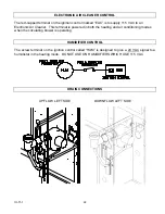
Page 22: ...is terminal is powered in both the heating and air conditioning modes when the circulating blower is operating HUMIDIFIER CONTROL The screw terminal on the ignition control called HUM is designed to give a 24 VAC signal to a humidistat in the heating mode DO NOT USE ON HUMIDIFIERS WHICH USE 115 VAC DRAIN CONNECTIONS UPFLOW LEFT SIDE DOWNFLOW LEFT SIDE ...

Page 23: ...IO 151 23 DOWNFLOW RIGHT SIDE UPFLOW RIGHT SIDE HORIZONTAL LEFT HORIZONTAL RIGHT ...

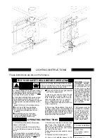
Page 24: ...Move the gas control switch or knob above on this label If you don t smell Follow B in the safety information 7 Wait five 5 minutes to clear out any the control system and any gas control the appliance and to replace any part of a qualified service technician to inspect has been under water Immediately call D Do not use this appliance if any part tools If the gas control switch or knob control swi...

Page 25: ...IO 151 25 ...

Reviews: